06-2023 dormakaba Canada Inc. RAC5 MFC Installation Guide – PK3738 | 17
6 Annex B: Multi-Floor Controller RAC5 MFC
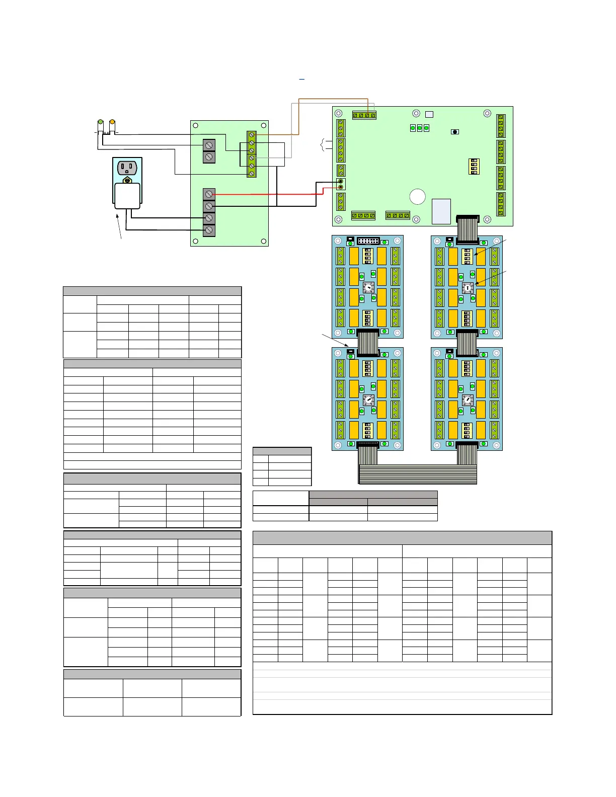
Figure 8 RAC5 MFC
1 2 3 4
1 2 3 4
1 2 3 4
J17
J3
J7
J8
J12
J1
J15
J16
J6
J18
J19
RAC5 MFC PCB
NO NC COM
GND FIRE GND 12V_LCK#1
GND 12V NO NC COM
RE_UNL#2
GND
RE_UNL#1
1 (+) 2 (-) 3 (+) 4 (-)
1
2
3
4
1
2
3
2
1
1
2
3
12_LCK#2 GND
1 2 3 4
PWR GND GND PWR
RD#1 RD#2
READER 2 READER 1
1 2 3 4
J11
REX2 GND
TAMPER
GND
DOOR
STAT#2 GND
GND
REX#1
GND
DOOR
STAT#1
GND
GND LOW_BA T AC_F AIL
4 3 2 1
Access Override Connection
Relay Bypass
Switch [SW1,
SW3]
(used for test
purposes
only)
O N
1 2 3 4
1
0
5
23
85
6
7
1234
5
6
7
8
1 4
O N
1 2 3 4
5 8
3 C 1 3 C 1 3 C 1 3 C 1
1 C 31 C 31 C 31 C 3
O N
1 2 3 4
1
0
5
23
85
6
7
1234
5
6
7
8
1 4
O N
1 2 3 4
5 8
3 C 1 3 C 1 3 C 1 3 C 1
1 C 31 C 31 C 31 C 3
O N
1 2 3 4
1
0
5
23
85
6
7
1234
5
6
7
8
1 4
O N
1 2 3 4
5 8
3 C 1 3 C 1 3 C 1 3 C 1
1 C 31 C 31 C 31 C 3
Relay
Board ID
Selector
[SW2]
(switch sets
the unique
board ID)
O N
1 2 3 4
DELAY0
DELAY1
DEVICES
TEST MODE
SW2
D46D37D48
SW1
Reset
O N
1 2 3 4
1
0
5
23
4
85
6
7
1234
5
6
7
8
1 4
O N
1 2 3 4
5 8
3 C 1 3 C 1 3 C 1 3 C 1
1 C 31 C 31 C 31 C 3
RELAYS ON
RELAYS OFF
SW4
4
RELAYS ON
RELAYS OFF
SW4
4
RELAYS ON
RELAYS OFF
SW4
4
RELAYS ON
RELAYS OFF
SW4
Relay State
Switch [SW4]
(switch sets idle
state of relays
after power-up
per board – all
boards must have
SW4 configured
identically)
12V GND
Power Supply
NO C NC
NO C NC
LOW BATT
AC FAIL
DC OUT
+ -
BAT
+ -
INPUT
XFRM
Power Adaptor
Power
Status
Battery
Status
NOTE: J3, J7, J8 & J11 inputs (max source current of 25mA) are all connected to dry
terminals (NC, NO) with a common connection to the Ground terminal on each of
the connectors; dry terminals must be able to sink minimum 25mA at a minimum of
5V rating. J1 is rated for an output of 12V @ 200mA.
Multi-Floor Controller RAC5 MFC
dormakaba Canada Inc. - PK3745
B
Idle state after power up Relays normally OFF Relays normally ON
Valid keycard state Relays turn ON Relays turn OFF
J1-1 NO J5-1 NO J1-1 NC J5-1 NC
J1-C COMM J5-C COMM J1-C COMM J5-C COMM
J1-3 NC J5-3 NC J1-3 NO J5-3 NO
J2-1 NO J6-1 NO J2-1 NC J6-1 NC
J2-C COMM J6-C COMM J2-C COMM J6-C COMM
J2-3 NC J6-3 NC J2-3 NO J6-3 NO
J3-1 NO J7-1 NO J3-1 NC J7-1 NC
J3-C COMM J7-C COMM J3-C COMM J7-C COMM
J3-3 NC J7-3 NC J3-3 NO J7-3 NO
J4-1 NO J8-1 NO J4-1 NC J8-1 NC
J4-C COMM J8-C COMM J4-C COMM J8-C COMM
J4-3 NC J8-3 NC J4-3 NO J8-3 NO
If SW4 is in the OFF position when the bypass switches (SW1 and SW3) are "OFF", then GREEN LEDs are "OFF" & Controller Board
can activate the relays
If SW4 is in the ON position when the bypass switches (SW1 and SW3) are "ON", then relays are bypassed & GREEN LEDs are "OFF"
If SW4 is in the ON position when the bypass switches (SW1 and SW3) are "OFF", then GREEN LEDs are "ON" & Controller Board
can activate the relays
If SW4 is in the OFF position when the bypass switches (SW1 and SW3) are "ON", then relays are bypassed & GREEN LEDs are "ON"
NOTE: Boards are shipped with SW4 in the OFF position with tape seal
Descritpion Item* Signal PCB Conn.
Black Fire Alarm J18 pin 3
MFC PCB Peripherals Connections
Type Wire Color Signal ID
Power Supply to Power Adapter
• Relay Switch SW4 determines the
idle state of the Relays after a power
up and when the System is ON.
• The table below describes the
terminals after power up and during
IDLE state with the bypass switches
(SW1 and SW3) OFF.
LED Description
D37 Reader 2 Online
D46 Heartbeat
D48 Reader 1 Online
Signal ID Wire Color Signal
AC Fail-1 NC Orange ( - )
Low Bat-1 NC Yellow ( - )
Signal Reader Config Reader # Term Block
12V Batt J1 pin 1 RD1 J4 +
12V Batt J1 pin 4 RD2 J4 +
RD2 Data + J12 pin 1 RD2 J5 TXP
RD2 Data - J12 pin 2 RD2 J5 TXM
RD1 Data + J12 pin 3 RD1 J5 TXP
RD1 Data - J12 pin 4 RD1 J5 TXM
Controller Board RAC5 Reader Connections
Wire connection to back of contactless card reader
J4 - (BLACK), J4 + (RED), J5 TXP (WHITE), J5 TXM (GREEN)
Wire Color Connector ID Signal ID
Red J16 pin 1 12V DC OUT +
Black J16 pin 2 GND DC OUT -
White J17 pin 1 AC_FAIL AC FAIL NO
Brown J17 pin 2 LOW_BAT LOW BAT NO
- J17 pin 3 GND - -
RAC5 MFC PCB to Power Supply