06-2023 dormakaba Canada Inc. RAC5 MFC Installation Guide – PK3738 | 6
2.2 Components
Refer to Annex D for RAC5 MFC component breakdown.
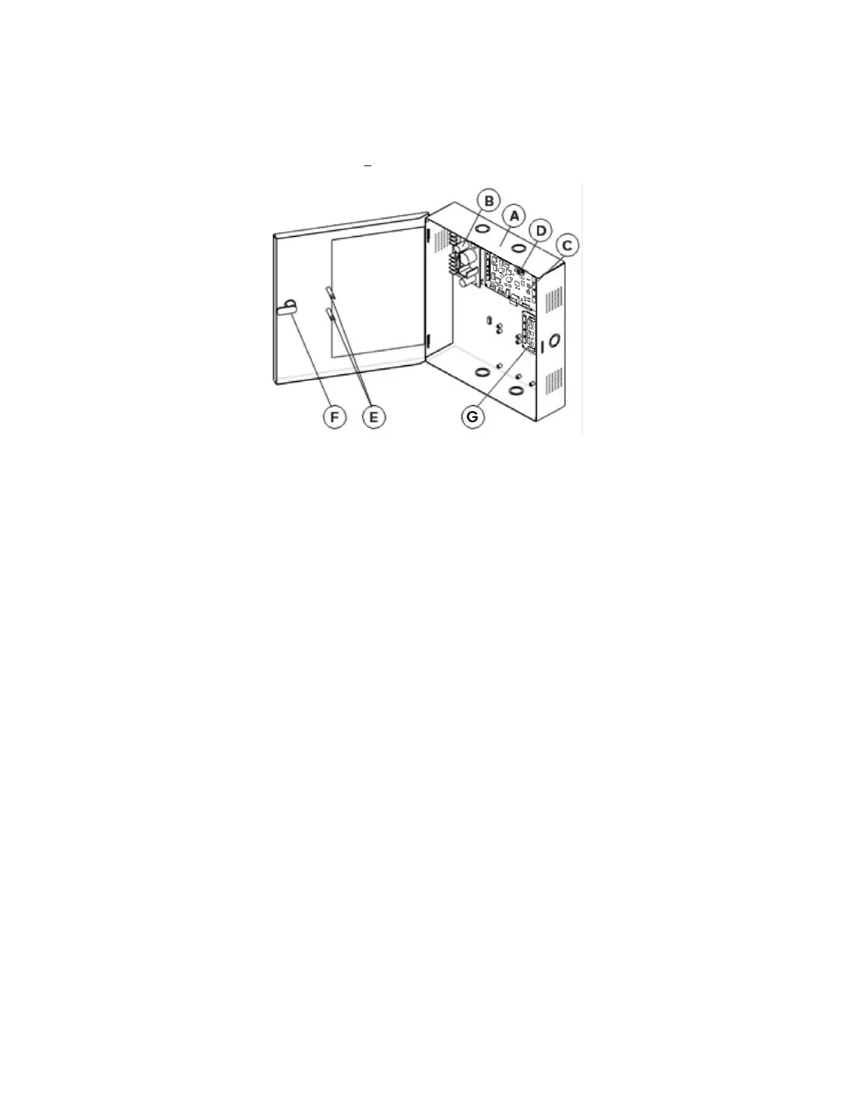
2.2.1 Controller Box
Figure 2 RAC5 MFC Controller Box
(A)
RAC5 MFC Enclosure & Access Door: Holds the controller board (PCB), power supply and relay expansion
board. Knockouts are available on 3 sides for routing of peripheral cables
(B)
Power Supply: Provides the DC power required for operation of the controller PCB and all peripherals
(C)
Controller Board: Controls all the features of the RAC5 MFC system
(D)
Tamper Switch: Attached to the RAC5 MFC enclosure to generate an alarm if the box is opened during
operation
(E)
Power & Battery Status LEDs: Provides visual indication of the operational status of the RAC5 MFC
system. Battery status LED is only used on battery back-up equipped systems
(F)
Cam-lock with Key: To provide secure locking and to control access to the RAC5 MFC enclosure
(G)
Relay Expansion Board: Interface board providing 8 relay outputs that can be used to control relay-
equipped equipment. For example, it can be used with an elevator to call the elevator or to provide
access only to specific floors for certain guests and staff. Up to 8 expansion boards of 8 relays each
giving up to 64 individual control relays can be added
Not Shown:
(H)
Cables: Cables required for connections of the LEDs, power supply and controller PCB. If equipped, will
also include cable for connection of relay expansion board