20
21
ink. The given mode is distinguished by a periodical switching over of the
angle of incidence of the top white light to the banknote. Due to this, the
banknote security mark printed in the variable color ink alternately changes
its color. The color of the marks shall change within the limits specified in de-
scription of the banknote security features. If a mark on the banknote does
not change its color in compliance with the description, the banknote may
be counterfeited, that‘s why the other authenticity marks need verification .
Visibility of the mark shall change on banknotes of some currencies, for ex-
ample, on euro banknotes. Next pressing of the DL key switches off the
white illumination source.
CONTROL WITH VERIFYING IN WHITE TRANSMITTED LIGHT AND
IR TRANSMITTED LIGHT
Place a banknote or a document on the viewing table. Press the DL key () to
switch on the bottom illumination source (the “Bottom White + IR” message
will be displayed). The source inside the viewing table is emitted
simultaneously white light and transmitted IR light;
meanwhile the top source of IR light is switched off. The mode is good for
verification of the watermarks and imprinted metalized stripes with drawing,
micro perforations etc. The screen shows the image obtained at its
transmission by IR-rays. It makes possible to examine watermarks and
markings on the metalized stripes with better contrast;
this mode is good for Euro banknotes control. The best way of micro
perforation control is 10x zoom mode. The authentic holes of micro
perforations are located with a constant pitch, have a round form and the same
size; there is not observed any darkening of paper or its thickening at their
edges.
SIZE CONTROL
To check the dimensions of the banknotes and the accuracy of the sepa-
rate marks located on them, use the control scale applied on a matt glass
of the viewing table.
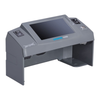
UNIVERSAL COUNTERFEIT DETECTOR DORS 1300 UNIVERSAL COUNTERFEIT DETECTOR DORS 1300
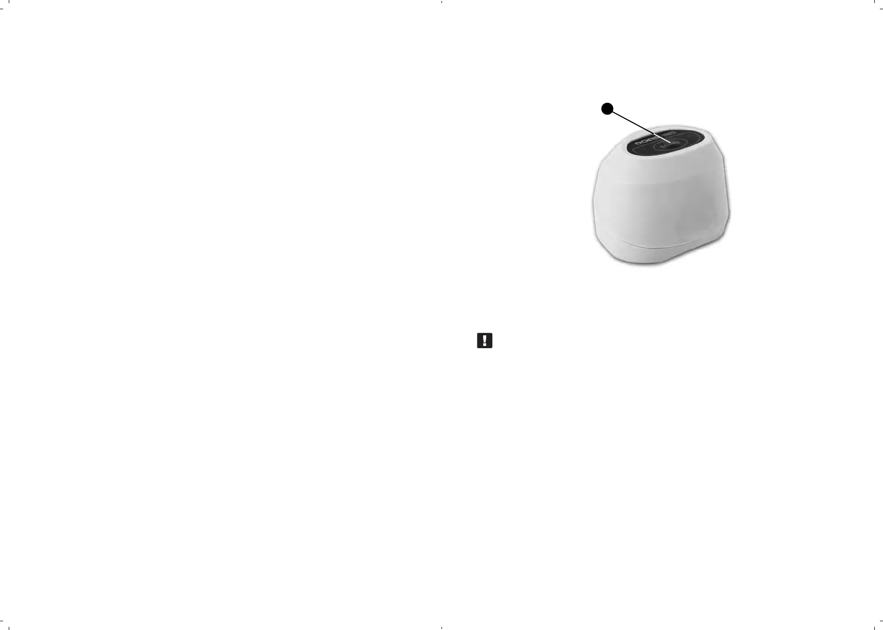
OPERATION WITH EXTERNAL VIDEO MAGNIFIER DORS 1020
Connect video magnifier DORS 1020 (Fig. 5)
to jack V1 or V2 on the device rear panel.
SELECT key
Fig. 5. Video magnifier DORS 1020
ATTENTION! BEFORE CONNECTION AND DISCONNECTION OF
THE MAGNIFIER CABLE, MAKE SURE THE DEVICE HAS BEEN
DISCONNECTED FROM THE POWER SOCKET OR SWITCHED
OFF WITH A POWER SWITCH!
Switch on the device. Press (in case of the SELECT key on the top
of the magnifier.
The device automatically switches to the mode of image examination through
the magnifier. Further pressing of the given key makes possible selection
of the required illumination source. Magnifier DORS 1020 has three light
sources:
white, IR and UV. The message in the top part of the screen
indicates the examination mode.
Long pressing of the TV key () switches the device for viewing with
the built-in camera. Returning to operation with the video magnifier requires
one more long pressing of the TV key, or pressing of the SELECT key ()
on the top of the magnifier.
23