8 9
Display
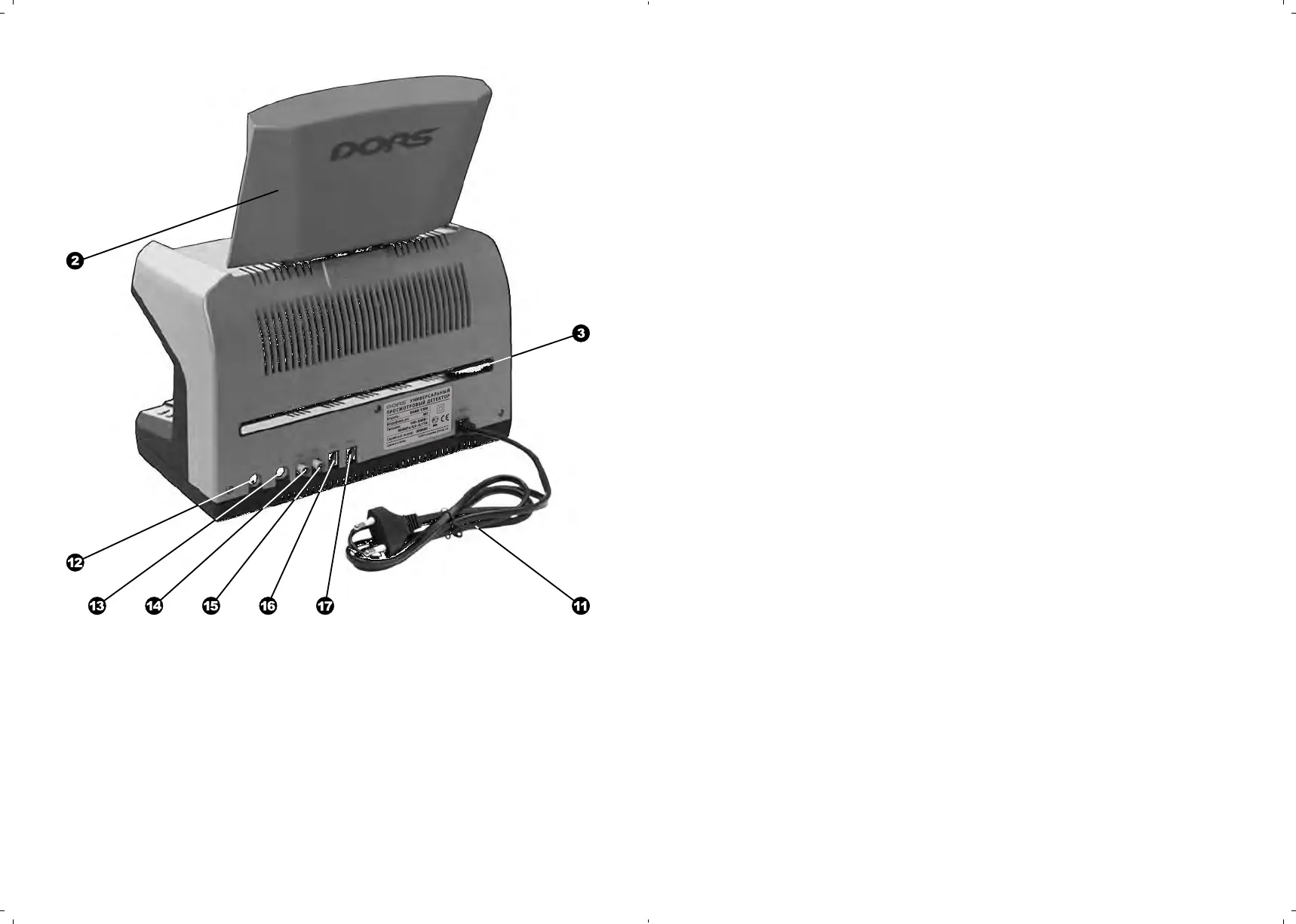
Slot for a large-sized document
Power cord
, C onnectors V1, V2 for DORS
1010 (DORS 1020)
Connector IN to connect to an
external video signal source
Connector OUT to connect to the
computer or an external display
, C onnectors M1, M2 to connect
DORS 10 (DORS 15)
Fig. 2.
Rear view
UNIVERSAL COUNTERFEIT DETECTOR DORS 1300 UNIVERSAL COUNTERFEIT DETECTOR DORS 1300
APPEARANCE
PREPARING FOR OPERA
TION
ATTENTION! BEFORE THE DEVICE OPERATION STARTS, MAKE
SURE ABOUT INTEGRITY OF ITS BODY AND THE THREE FLUORES-
CENT LAMPS
.
IT IS PROHIBITED TO CONNECT TO THE POWER SUPPLY THE
PRODUCT
WITH
A DAMAGED BODY, WITH THE DAMAGED UV-
LAMPS OR WITHOUT THEM.
The device is supplied in a package with display body in lower position
.
This
position of the display is for transportation or moving the device to a different
working place. The display body may be turned around the horizontal and ver-
tical axes to provide the best view. After the device has been installed on its
working place, it is necessary to lift the display body to its working position and
orient it is so that the operator’s glance would be perpendicular to the screen
surface.
If it is supposed to use additional external devices (DORS 15,
DORS 1020) during the device operation, they shall be connected to the
corresponding rear panel jacks before the device is connected to the
mains. Video magnifier DORS 1020 is connected to the jacks V1 or V2
(,), and DORS 15 detector of magnetic and IR marks — to the jacks
M1 or M2 (,).
To start the device operation, the power cord shall be connected to power
socket 110-240 VAC 50/60 Hz. Then to switch on the device, press the power
switch
.
A built-in red indicator will turn on showing that the device is switched
on. After a 7-10 second energizing, the display driver is initialized, the working
settings are loaded and the detector undergoes self-testing. Until this process
is finished, the device controls are disabled. Appeara n c e of “Self-testing...
Please wait!” on the screen means the self-testing stage has started. The first
switching on establishes the mode of the IR marks inspection in a reflected
light.