Installation
Dräger X-dock 5300/6300/6600 7
3 Installation
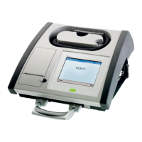
The maintenance station can automatically recognise the test
gases required for the instrument and cross-check them with
the connected and configured test gases.
The gas exposure sequence always results from the sequence
of the connected test gas cylinders.
The maintenance station has various safety mechanisms at its
disposal to prevent configurations critical to safety.
For example there are limitations with regard to specific test
gas concentrations or an automatic flushing process takes
place at the beginning of the test in case of high measured
values. Nevertheless, it is necessary for a qualified specialist
to design and approve the station for the required task.
The designer for example must take into consideration the
cross-sensitivities of the sensors with connected test gases
and consult the respective sensor data sheets. A description of
the tasks to be accomplished must be provided which in turn
determines which test method with which test gas
concentration is appropriate.
If the required expert knowledge is not available, it has to be
obtained from others (e. g. specialists, test institutions or
manufacturers).
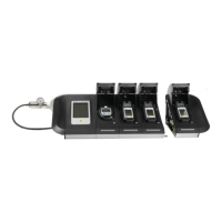
1. If applicable, install modules on the master station in
accordance with the assembly instructions (X-dock 6300/
6600 only).
A maximum of 10 modules can be installed on one
master station.
The available modules can be combined in any way
desired.
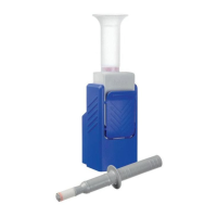
2. If applicable, install wall mount or cylinder holder in
accordance with the assembly instructions.
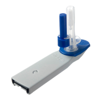
3. Remove the sleeves from the intended gas inlets and from
the gas outlet.
4. Fit the gas feed hoses to the gas inlets on the master and
connect them to the regulator valve on the test gas
cylinder.
5. If required, connect an exhaust hose (max. 10 m long) to
the exhaust outlet.
6. Ensure a supply of compressed air or fresh air:
Connect the compressed air hose to the compressed
air port (outlet pressure of pressure regulator valve
0.5 bar, flow rate >3 l/min).
Adjust fresh air input (see chapter 4.7.2 on page 12).
Setting: Supplied by compressed air input.
OR
If required, connect the fresh air hose to the fresh air
filter.
Adjust fresh air input if necessary (see chapter 4.7.2 on
page 12). Setting: Supplied by pump.
7. Connect the power pack.
Station with up to 3 modules: Power pack 24 V / 1.33 A
Station with 4 to 10 modules: Power pack 24 V / 6.25 A
The entire system is supplied with power via the master.
WARNING
Risk of personal injury and damage to equipment
through faulty maintenance of gas detection
instruments.
Unless the maintenance station is properly set up for
the scheduled tasks, there is a risk that gas detection
instruments are not checked and serviced as
expected.
Prior to initial operation the correct design and
dimensioning of the appropriately configured
instruments must be approved by a qualified specialist.
NOTICE
Ensure adequate space for the entire assembly.
The master and all modules must have the same
firmware version. If this is not the case, a firmware
update needs to be carried out (see chapter 9.4 on
page 26).
NOTICE
If the sleeve is not removed from the gas outlet, the station
will be unable to conduct the self-test without errors.
NOTICE
For the gas exposure sequence Dräger recommends
using toxic gases with increasing concentrations.
Dräger recommends not to exceed a hose length of
10 m for the gas supply hoses.
WARNING
Risk of personal injury!
Impurities of the ambient air may result in faulty
measurements.
If you use the internal pump to supply fresh air through
the fresh air inlet you need to ensure that the ambient
air is devoid of interfering substances.
NOTICE
Dräger recommends the use of Dräger test gas
cylinders and Dräger pressure regulator valves (see
chapter 12 on page 28). Alternatively there is the
option of using a suitable pressure regulator valve with
0.5 bar outlet pressure and
>3 L/min flow rate.
Dräger recommends connecting an exhaust hose
(max. 10 m long) to the exhaust outlet to discharge the
test gas into the open air.
i
i
i
i
!
i
i
 Loading...