17
Maintenance
● Switch off calibration gas and remove calibration adapter.
● Wait until the measured value drops below the alarm threshold set on the central
unit. Otherwise an alarm will be triggered when the maintenance switch is re-
turned to the measuring position immediately after calibration.
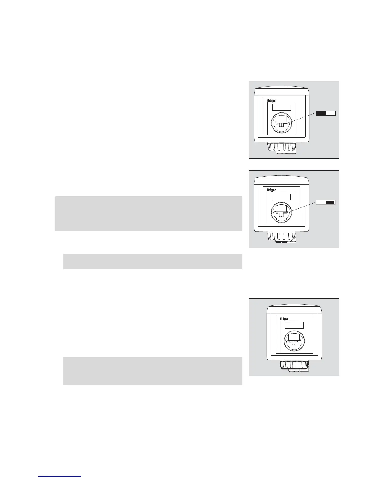
1 Set maintenance switch to measuring position, left-hand position. The 4 to 20 mA
output changes to measuring mode.
● Refit the front cover of the service port and lock it in place by turning clockwise
with an Allen key (approx. 60
o
).
Replacing the sensor
The sensor can be replaced, if necessary, without interrupting the power supply in
the explosion-hazard area.
Use only DrägerSensors which are approved for use with the Dräger Polytron 3000
transmitter.
● Open the front cover of the service port with an Allen key by turning anticlockwise
(approx. 60
o
). The maintenance switch and potentiometers for calibration are now
revealed.
1 Set maintenance switch to right-hand position. The 4 to 20 mA output changes to
maintenance mode. In this position, a maintenance signal is relayed to the ana-
logue output and prevents alarms being triggered.
2 Remove bayonet ring from transmitter; pull out old sensor.
3 Remove sensor from packaging. Ensure that the sensor is of the same type as that
specified on the sticker on the measuring unit.
● Remove the short-circuit strap from the sensor (if it is fitted).
● There is a coded connector on the back of the sensor. Place the sensor in the
opening with the connector at the back and the Dräger logo at the front.
Before plugging the connector in the socket, ensure that they are identically cod-
ed. Incorrect connection can damage the sensor!
2 Secure sensor in transmitter with bayonet ring.
● Wait until the measured value drops below the alarm threshold set on the central
unit. Otherwise an alarm will be triggered when the maintenance switch is re-
turned to the measuring position immediately after the sensor replacement.
Caution:
— When the transmitter is installed in Ex areas zone 22 or Class II, Div. 1 & 2,
Group E, F, G the opening of the housing (inclusive sensor replacement)
must not be done when connected to power (power must be turned off or
the area has to be declassified)! Explosion hazard!
Attention!
Use only a 5 mm Allen key without a ball head.
Attention:
For use in Zone 22, tighten the locking screw (2 mm Allen screw) of the
sensor bayonet ring tight enough to ensure that the bayonet ring is
secured against unintended loosening.
02023758_1.eps
Polytron
1
02123758_1.eps
Polytron
1
02223758_1.eps
Polytron
2
3