34
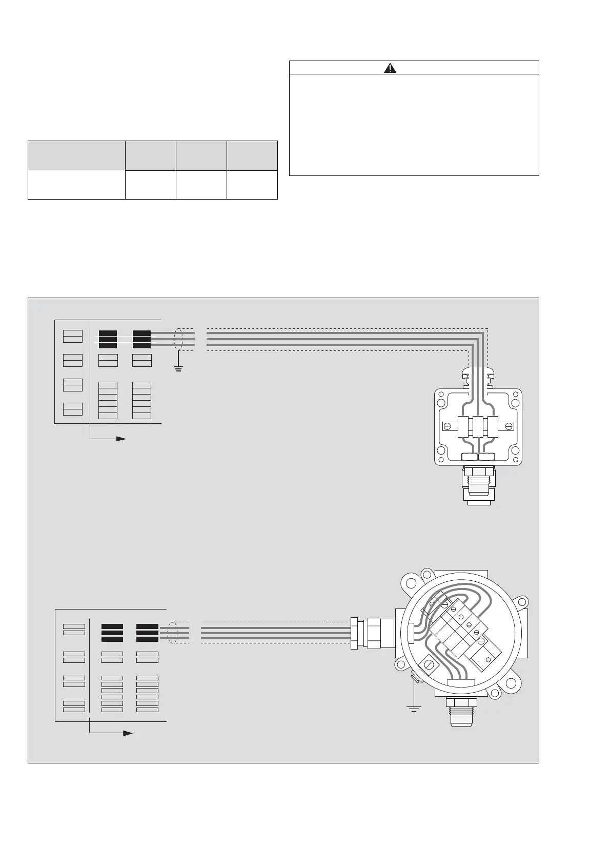
Connection to Controller Unit Polytron with
Channel Module Polytron SE Ex
– The cable resistance must not exceed 20 Ohms per
core.
This results in the following maximum distances for the
various cross-sections:
z Connect terminals 1, 2 and 3 of the sensing heads
with the terminals 1, 2, and 3 of the device rack as
shown.
z Carefully connect all wires of the signal cable.
The signal cable has to be selected in accordance to
local electrical codes and the temperatures it will be
used in.
This drawing is exemplary for sensing heads
Polytron SE Ex PR M1 DD / Polytron SE Ex LC M1 DD
and Polytron SE Ex HT M DD:
Core
cross- section
1.0 mm
2
1.5 mm
2
2.5 mm
2
maximum cable
length
950 m 1450 m 2400 m
CAUTION
Remark concerning shielding:
The metallic housings of the sensing heads Polytron
SE Ex HT M DD, Polytron SE Ex PR NPT1 DD and
SE Ex LC NPT1 DD need to be earthed at side by
means of their external PE-terminals. To avoid double
earthing it is recommended to connect the cable
shielding to the internal PE-terminal of the housing and
not to the PE-terminal at the controller site.
1
+
–
2
3
00633176.eps
12
3
12
3
Polytron SE Ex
1 ... 12
PE
1
2
3
4
4
Polytron SE Ex
3
2
1
+
–
1 ... 12
3
2
1
3
2
1
 Loading...