67
TESTS & ALIGNMENTS
Step 4: Align Axis A-B (Y-Axis)
using Alignment Laser's Red Dot.
Conceptually, you will be aligning the
invisible cutting beam and the Alignment
Laser's visible red dot with the axis of the
shaft from A to B. When the beams are
perfectly parallel with the A-B axis, do
not continue to change Mirror #1. Further
changes to Mirror #1 will then negate the
alignment to the axis.
1. Open the Lid.
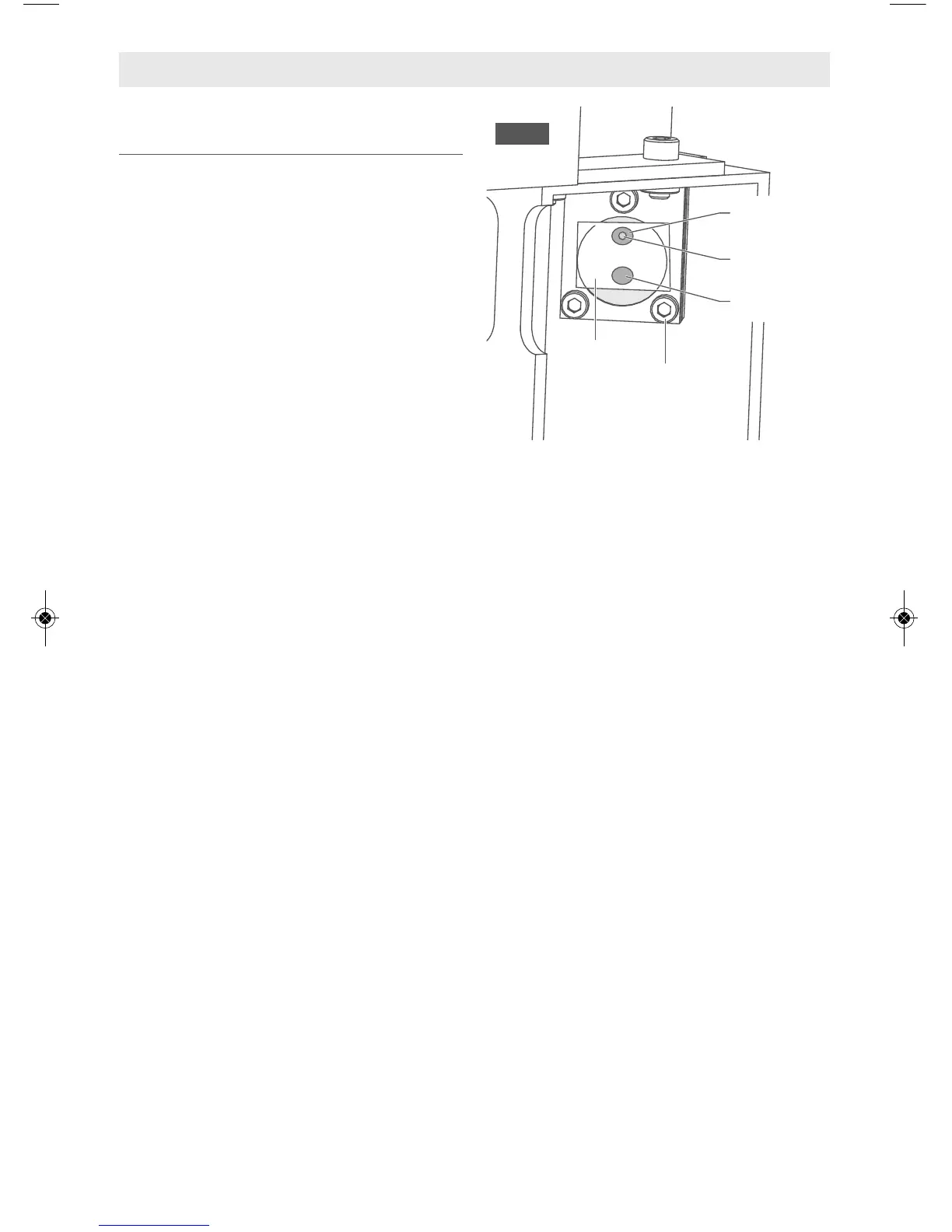
2. Place Thermal Paper: Take a small
piece of thermal paper (approximately
1 inch (25 mm should be plenty) and
place it firmly over Mirror #2, Fig. 36.
3. Press the paper down with a finger so
that a circle appears that
demonstrates the outer rim of Mirror
#2. Sometimes pencil lead or crayon
will help to show the edges of the lens
and mirrors.
4. Move the Gantry to position B, Fig. 29.
5. Close the Lid.
6. *Test Fire* Observe where the spot
lands through the Lid. Without
removing the paper it may be
necessary to mark this spot. This is
Spot B1.
7. Adjust only the visible red dot to
match the spot.
a. Do not move the Gantry at this
time, and do not adjust Mirror #1
yet.
b. Using the 2.5mm hex wrench, make
micro adjustments to the three
adjustment screws of the
Alignment Laser, and position the
red dot exactly over the burn mark
at position B on Mirror #2.
c. If the red beam is not hitting the
mirror at all, it may be necessary to
use a larger card or paper to
determine where the red dot is.
d. Go slowly and do not overtighten
screws. Small turns of the screws
are required to move the beam at
long distances.
e. It is best to align the red dot at the
furthest distances B and C to avoid
small angle issues introduced at A
or D.
8. Without removing the paper, move the
Gantry to A.
9. *Test Fire*. If possible change position
to see if the test fire lands on the
thermal paper without opening the
Lid. If it is not possible it may be
necessary to use the suggested marks
in step 6. This is Spot A1.
If the two spots are exactly on top of
each other, then the Y axis is aligned.
Do not make any more changes to M1.
Move on to B-C X axis alignment.
10. If the 2 spots are not on top of each
other at A and B, continue as follows:
a. Move the Laser Head back to
position B.
b. Note that the red dot can now be
used to predict where the next
laser fire shots will be if it is
aligned as in step 7.
c. While at position B, slowly adjust
Mirror #1. Not the red dot!
d. Change the mirror so that the red
dot moves halfway toward Spot
A1.
e. Leave the Gantry at B, Close the
Lid and tap *Test Fire*.
 Loading...