69
Step 6: Align Axis Lens holder
(z-Axis) using Alignment Laser's
Red Dot
Centering of the beam on the lens is the
most critical component of alignment.
However, as the distance from Mirror #3
to the lens is very short, it is difficult to
make drastic changes to the position of
the laser spot. Resist the urge to adjust
Mirror #2 or Mirror #1, because as
indicated before, it will only create
misalignment.
1. Open the Lid.
2. Place Thermal Paper: Take a small
piece of thermal paper (approximately
1 inch (25mm) should be plenty) and
place it firmly over the lens.
3. Press the paper down with a finger so
that a circle appears that
demonstrates the outer rim of the
lens. Sometimes pencil lead or crayon
will help to show the edges of the lens
and mirrors.
4. Move the Gantry to Position C.
5. Move the lens to its lowest position
using the Spacer Puck on the
Honeycomb Plate.
6. Close the Lid and tap *Test Fire*
without removing the paper as it may
be necessary to mark this spot. This is
Spot L1.
7. Tweak the red dot to match the spot
on the paper. Due to the reflections of
all of the mirrors the red dot may not
move with the same screw turns as it
did previously.
8. Adjust Mirror #3 continuing to test fire
until the spot is nearly perfectly
centered.
a. Note: do not overly tighten Mirror #3.
b. In rare instances, it may be
necessary to access the Mirror #3
mounting screws.
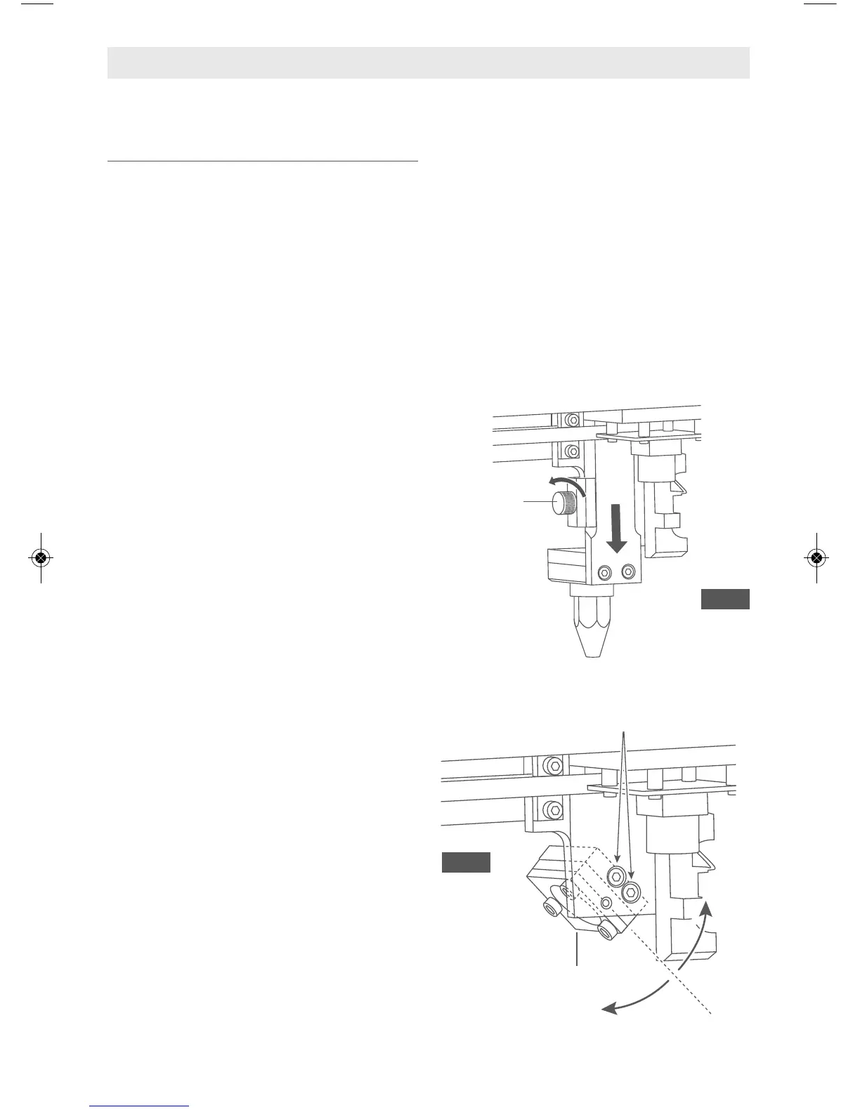
c. Fully remove the lens holder
assembly by loosening the Laser
Head Knob, Fig. 37.
d. Loosen the two Mirror #3 mounting
screws (Fig. 38) enough to rotate
the lens in the direction of the
missing spot. While holding the lens,
retighten. The screws tend to rotate
the mirror in the direction of
tightening.
e. Replace lens holder assembly.
9. After the spot is centered rerun the 4
Corners Tests. The spots should now
be nearly on top of each other. Also be
sure to check that the Air Assist Nozzle
is not clipping the laser path and
adjust if necessary.
TESTS & ALIGNMENTS
Fig. 37
Fig. 38
Laser Head
Knob
Mounting Screws
Mirror #3
 Loading...