-10-
3.1 Inputting Motor Data
(1) Press the FUNC key.
(2) Select code number 16. Press the SET key, select
SP, set-2 with the up or down arrow keys, and press
the SET key again.
(3) Change the code number displayed on the console
one by one with the up or down arrow key.
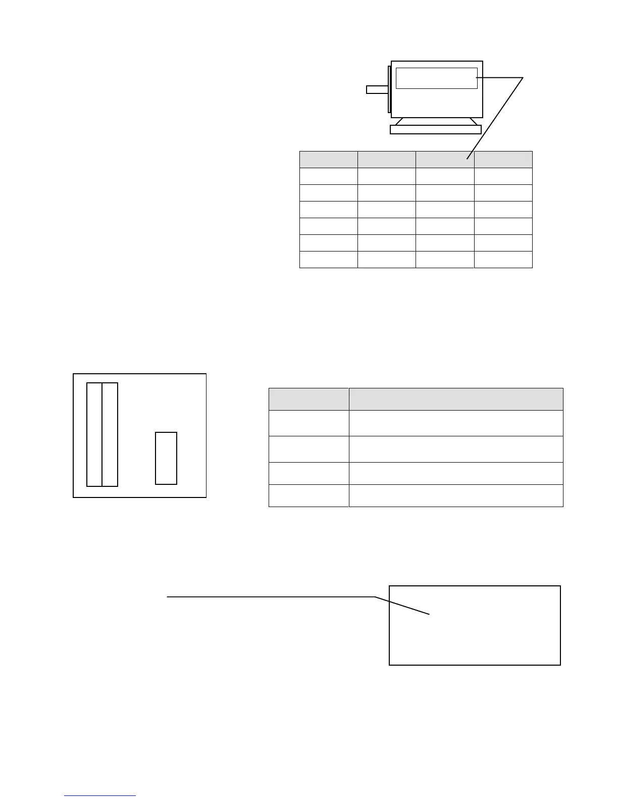
Set the data shown on the right according to the
rating indicated on the name plate of the motor.
(The above table shows the factory set values of t he inverter model
7r522)
Code # Functions Set items Data
17 Motor.Cap Rated capacity 7.5kW
18 Motor.V Rated voltage 200V
19 Motor.I Rated current 30A
20 Motor.F Rated frequency 60Hz
21 Motor.RPM Rated revolution 1740 rpm
22 Motor.Pole Number of poles 4 pole
Name plate
Motor
Set the values
shown on the
name plate of
the motor.
r1-ch is displayed on the 7-segment LEDs on the VFC61.
(3) Press the OPR key on the console to select the
operation mode. Make sure that the DIR mode is
established.
Press the START key. (Current flows to the motor)
(4) After approximately 20 seconds, r1END is
displayed on the 7-segment LEDs in the upper part
of the unit, indicating that automatic measurement is
completed.
Open the console to the right again. Set switch 3 of
SW1 on the control PCB (VFC61) to OFF. Data
has been set now.
* OPERATION *
DIR/STOP/FOR
(0.0) FOUT
0.0 [Hz]
Display on console
VFC61
4
3
2
1
ON
SW1
3.2 Automatic Measuring Operation
(1) Open the cover. Open the console to the right.
(2) Set switch 3 of SW1 on the control PCB (VFC61) to ON.
Pin # Functions
1
Inputted data is cleared and reset to the standard
data.
2
For manufacturer’s adjustment.
(Do not set this switch to ON)
3 Automatic measuring mode.
4 Data protection
Note the following functions of switches 1 to 4 of SW1.