11/29
4. FIXING AND INSTALLATION DETAILS
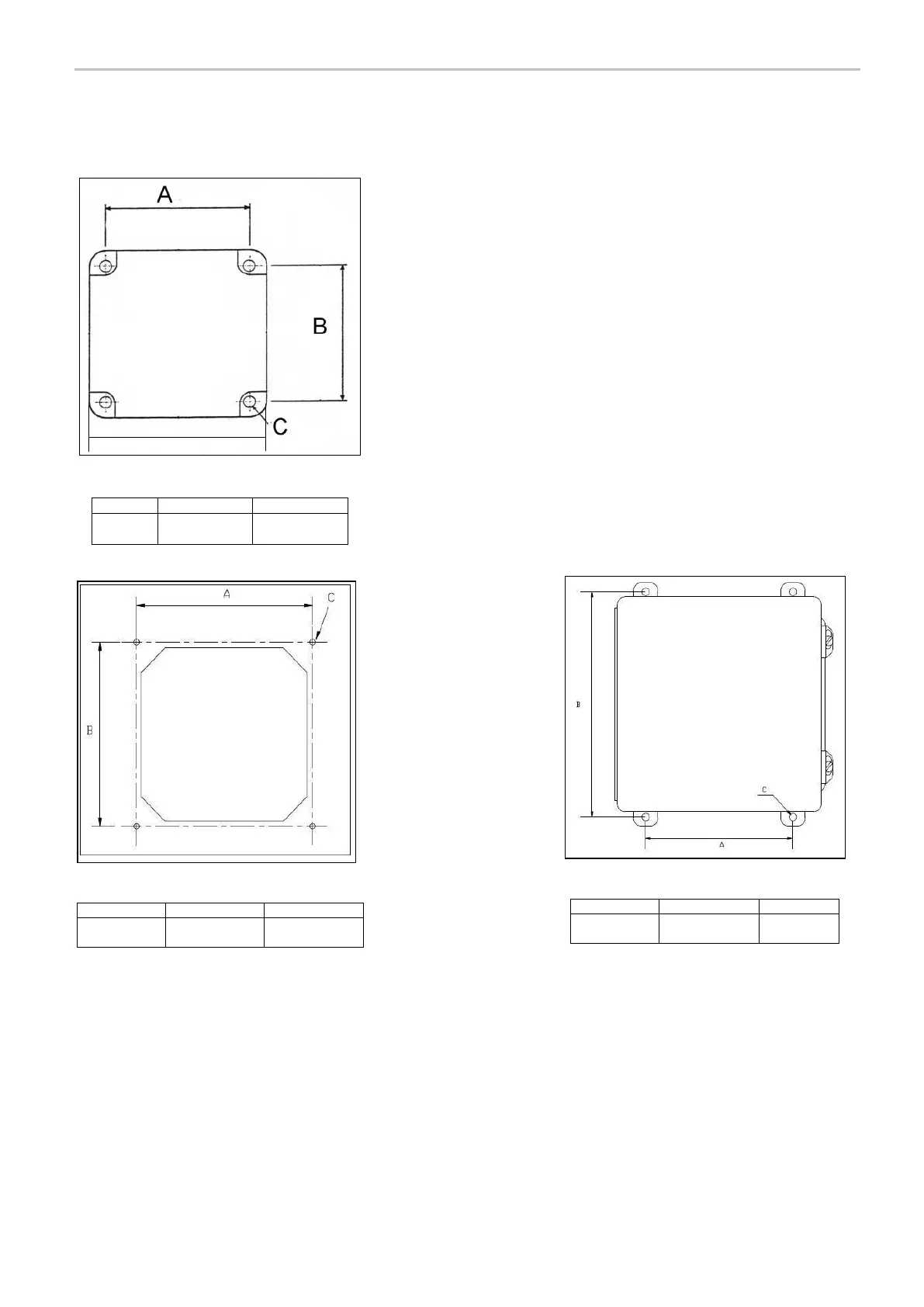
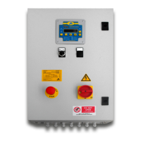
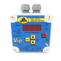
FIXING DIAGRAM
The different VIP5 models are shown below with fixing dimensions.
4.1 UN-PACKING
Once the installation point has been identified, you can unpack the VIP5 from its shipping box. Check that the unit has
not been subject to any damage during transport. Dispose of the packaging in an appropriate manner, following local
waste regulations.
4.2 INSTALLATION
The VIP5 must be secured physically to a mounting location and cabled to all the required components of the
lubrication system.
PN: 1639144 / 1639145/ 1639147
PN: 1639150 / 1639151 / 1639152 / 1639153
PN: 1639140 / 1639141 / 1639142