12/29
The following are general recommendation:
• Install the unit in an easy to access location so that users can avoid unnatural postures and have good visibility of the
display.
• Leave 100mm or 4 inches around the unit of space to facilitate cabling and maintenance.
• Do not install the unit in dangerous or excessively aggressive environments with high levels of vibration or in the
vicinity of flammable substances.
• Always use the four fixing points as indicated in the diagram.
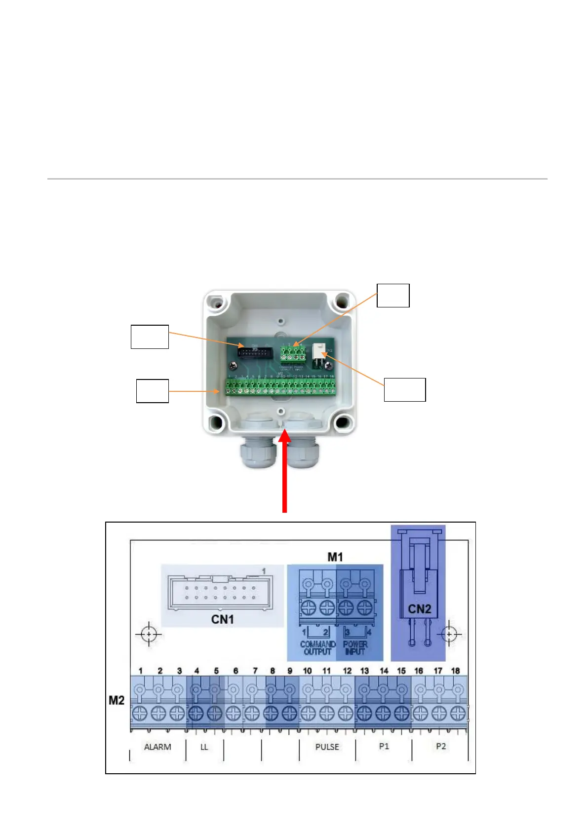
5. INPUTS/OUTPUTS
5.1 ELECTRICAL CONNECTIONS
The input and output connections for the lubrication devices and sensors can be achieved via the M1 and M2 terminal strip
located on the bottom of the VIP5 box.
The following are connection information for the M1 and M2 terminal strips.