For the 7kW version, the restrictor (supplied) is mounted
on the combustion fan. Please note the restrictor is part
of the venturi on the combustion fan.
For the 7kW Power Flue, the restriction is 22.5 mm when
using natural gas and propane.
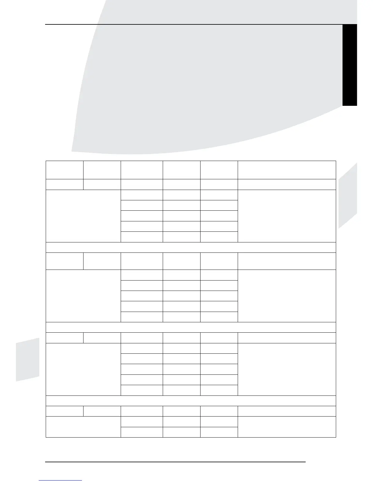
In Table 2 below, you can see the settings of the
restriction in relation to the construction of the discharge
system and the type of gas that is used
At the 12kW and 16kW versions, the restriction – if
necessary – will be placed in the flue gas discharge
connection of the manifold, with a heat-resistant sealant
(see fig. 7).
At the 12kW Power Flue, a restriction is only required if
the appliance is connected directly to the wall-terminal.
When using natural gas, the restriction will be 36 mm, and
when using propane 45 mm.
For the 16kW Power Flue, a 45 mm restriction is also
only required in case of a direct connection to the wall-
terminal. This value applies to the usage of both natural
gas and propane.
INSTRUCTIONS FOR INSTALLATION
Type Type of gas Number of
90º bends
tube length
(meter)
Restriction
(mm)
Remarks
7kW G20/G31 0 0 22,5
Direct connection to wall-terminal
0 1-10 22,5
1 1-10 22,5
Restriction is a fixed part
2 1-10 22,5
of venturi tube
3 1-6 22,5
4 1-2 22,5
12kW G20 0 0 36
Direct connection to wall wall-
terminal
0 1-10 none
1 1-10 none
2 1-10 none
3 1-6 none
4 1-2 none
G31 0 0 45
Direct connection to wall-terminal
0 1-10 none
1 1-10 none
2 1-10 none
3 1-6 none
4 1-2 none
16kW G20/G31 0 0 45
Direct connection to wall-terminal
0 1-3 none
1 1-3 none
Table 2: Relations between restriction, discharge system construction and type of gas
Kamara
9
English