6. Operating the appliance
6.1 Control panel
The control panel is located under the cover at the top of
the appliance.
The cover is provided with a lock.
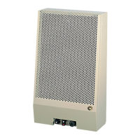
On the panel you will find (see fig. 11)
a) summer/winter switch;
b) thermostat;
c) lock-out mode;
d) reset button;
e) fuse.
sub a)
“0” position
In the position “0”, the appliance is switched off
winter position
In the winter position, you have 2 options:
1) The appliance is controlled by an external clock and/or
thermostat;
2) The appliance is only controlled by the internal
thermostat.
summer position
In the summer position the appliance will operate
independently from an external clock and/or thermostat.
In this position, only convection air (= surrounding air) is
circulated.
Sub b)
The (internal) thermostat can be set between 5 ºC
and 35 ºC.
The green led of the thermostat will light if the appliance
is switched on and the thermostat is “not requesting”.
The red led will light if the appliance is switched on and
the thermostat is “requesting”.
Sub c)
In case of a malfunction, the red lamp of the lock-out
mode will light.
Sub d)
In case of a malfunction, the appliance can be reset by
using the reset button.
6.2 Switching on the appliance for heating
• Set the external clock and/or thermostat, if present.
• Set the thermostat to the required temperature.
• Set the switch to the winter position.
Caution About approximately 30 seconds after
igniting the burner, the convection fan
should switch on.
The louvre openings will release warm air.
6.3 Switching on the appliance for air
circulation
• Set the switch to the summer position.
The appliance will continuously circulate convection air
(= surrounding air).
6.4 Switching off the appliance
• Set the switch to the “0” position.
7. Final check
To check that the appliance is operating correctly and
safely, you must proceed as follows before the appliance is
used.
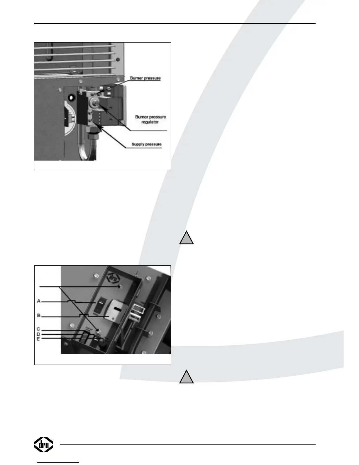
7.1 Gastightness
Caution All connections must be gastight.
!Caution The supply pressure to the gas control
valve cannot exceed 50 mbar.
• Check the connections for gastightness.
• Make the connections gastight, if necessary.
INSTRUCTIONS FOR INSTALLATION
12
!
!
Fig. 11
SCREWS
(behind cover screw)
Fig. 10
test point
test point