5.5.2 Installation of wall-terminal and manifold
Follow the procedure below when installing the wall-
terminal and manifold:
• Drill a hole in the wall, with a diameter of 105 mm.
• Drill 3 holes in the wall from the outside, for mounting
the wall-terminal.
!Caution - Place the wall terminal with the groove/
folded seam at the top;
• Glue the sealing/gasket of the wall-terminal to the flange.
• Temporarily mount the wall-terminal from the outside.
• Slide the manifold from the inside as far as possible onto
the concentric tubes of the wall-terminal.
• Determine the distance between manifold and wall.
• Unscrew the wall-terminal.
• Cut the wall-terminal to size.
• Mount the wall-terminal for the final time.
• Determine in which angle the manifold should be placed.
• Apply a sufficient amount of heat-resistant sealant to the
outside of the galvanized steel combustion air supply tube.
• Apply a film of heat resistant sealant to the inside of the
aluminium flue gas discharge tube.
• Place the sealing/gasket of the manifold between wall and
manifold.
!Tip For the manifold, you can choose between two
combustion air supply connections.
• Mount the manifold in the correct position.
• Drill 3 holes in the wall for mounting the manifold.
• Mount the manifold with the screws and washers supplied.
• If necessary, apply a wall-terminal guard.
• Place the wall-terminal guard centrally over the wall-
terminal.
5.6 Placing the appliance
Place the appliance as follows:
Caution - Do not make any changes to the
appliance;
- Do not cover the appliance and the
discharge material and/or do not wrap
it in an insulation blanket or any other
material;
- Mount the appliance to the wall using
the wall brackets; this will guarantee the
minimum required distance of 10 mm
from the back wall;
- Make sure there is a free outflow of
warm convection air at the front of the
appliance;
- Make sure there is a free supply of
cold convection air at both sides of the
appliance. Curtains, for example, could
block the inlet as a result of the sucking
action of the convection fan.
- Avoid that warm convection air can
recirculate through the cold convection
air inlet.
!Tip - Prevent construction grid/drill material from
contaminating the appliance;
- Only mount the casing, after performing the final
check in section 7.
• Provide a gas connection at the location. For details, see
section 5.3.
• Provide an electrical connection at the location. For
details, see section 5.4.
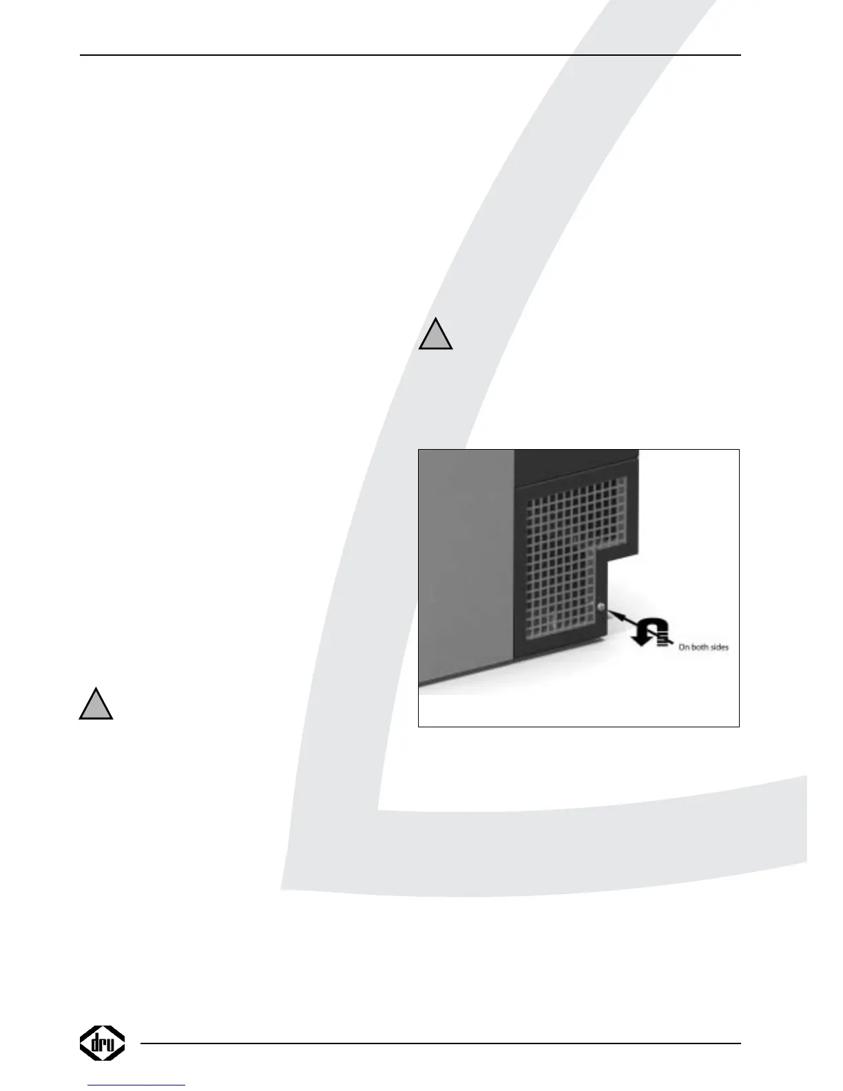
• Remove the casing:
- Unscrew the screws at both sides of the casing
(see fig. 4);
- Lift the casing appr. 1 cm and slide/lift the casing to the
front.
Caution Avoid damaging the wiring when taking off
the mantel.
• Place the appliance on its destined location.
• Drill holes for mounting the appliance.
• Attach the appliance to the wall, using the supplied plugs,
washers and screws.
5.7 Flue gas discharge / combustion air supply
system
5.7.1 Construction
For the 7kW and 12kW Power Flue, the maximum length
of the discharge tubes (vertical and horizontal) is 10
meters when using a maximum of 2 bends of 90º; when
3 bends of 90º will be used, the total maximum length of
the discharge system is 6 meters, and when 4 bends of 90º
will be used, the maximum length is 2 meters.
For the 16 kW Power Flue, the maximum length of the
discharge tubes (vertical and horizontal) is 3 meters, with
a maximum of 1 bend of 90°.
Depending on the construction, the appliance is set by
means of a restriction.
INSTRUCTIONS FOR INSTALLATION
8
!
!
Fig. 4