INSTRUCTIONS FOR INSTALLATION
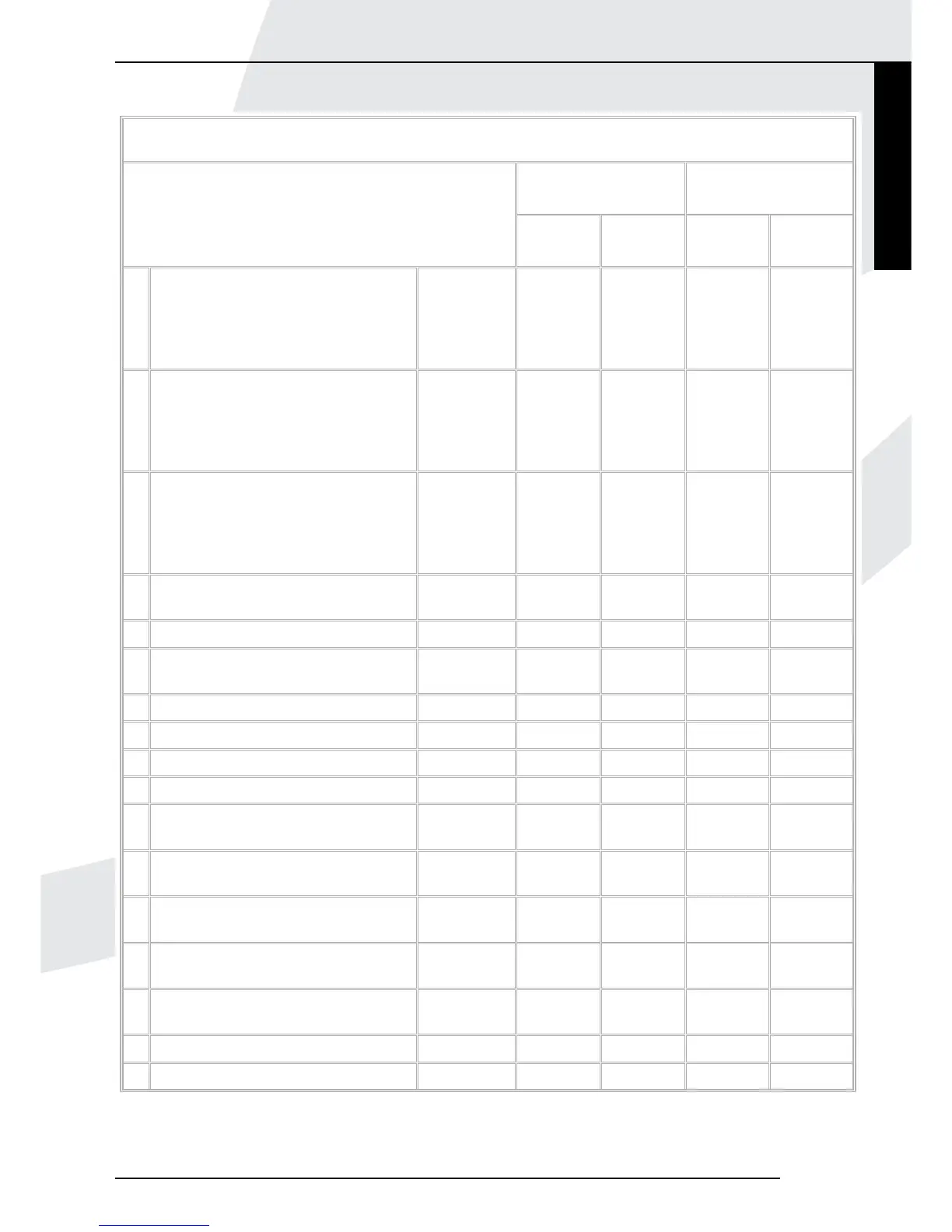
Minimum dimensions of flue wall-terminal positions
Balance flues
room sealed
Open flues
Wall-terminal position
Natural
draught
Fanned
draught
Natural
draught
Fanned
draught
A * Directly below an opening, airbrick,
window etc.
0-7kW
>7-14kW
>14-32kW
>32-70kW
300 mm
600 mm
1500 mm
2000 mm
300 mm Not allowed 300 mm
B * Above an opening, airbrick, window
etc.
0-7kW
>7-14kW
>14-32kW
>32-70kW
300 mm
300 mm
300 mm
300 mm
300 mm Not allowed 300 mm
C * Horizontally to an opening, airbrick,
window etc.
0-7kW
>7-14kW
>14-32kW
>32-70kW
300 mm
400 mm
600 mm
600 mm
300 mm Not allowed 300 mm
D Below a gutter or sanitary tube if
combustible material protected.
300 mm 75 mm Not allowed 75 mm
E Below eaves. 300 mm 200 mm Not allowed 200 mm
F Below balconies or open roofed out
buildings.
600 mm 200 mm Not allowed 200 mm
G From a vertical drain or soil tube. 300 mm 150 mm Not allowed 150 mm
H From an internal or external corner. 600 mm 300 mm Not allowed 200 mm
I Above ground or balcony level. 300 mm 300 mm Not allowed 300 mm
J From a surface facing the wall-terminal. 600 mm 600 mm N/A 600 mm
K From another wall-terminal facing the
wall-terminal.
600 mm 1200 mm N/A 1200 mm
L From an opening in the car port into a
dwelling.
1200 mm 1200 mm N/A 1200 mm
M Vertically from a wall-terminal on the
same wall.
1500 mm 1500 mm N/A 1500 mm
N Horizontally from a wall-terminal on the
same wall.
300 mm 300 mm N/A 300 mm
O From a wall on which the wall-terminal
is mounted.
N/A N/A N/A 50 mm
P From a vertical structure on the roof. N/A N/A 600 mm N/A
Q Above intersection with roof. N/A N/A 600 mm 150 mm
Notes: N/A = NOT APPLICAIABLE * In addition, the wall-terminal should not be nearer than 150mm (fan draught) or 300mm (natural draught) to an
opening in the building fabric formed for the purpose of accommodating a built-in element such as a window frame. Separation distances are linked to the
rated heat inputs as shown.
Kamara
7
English