3
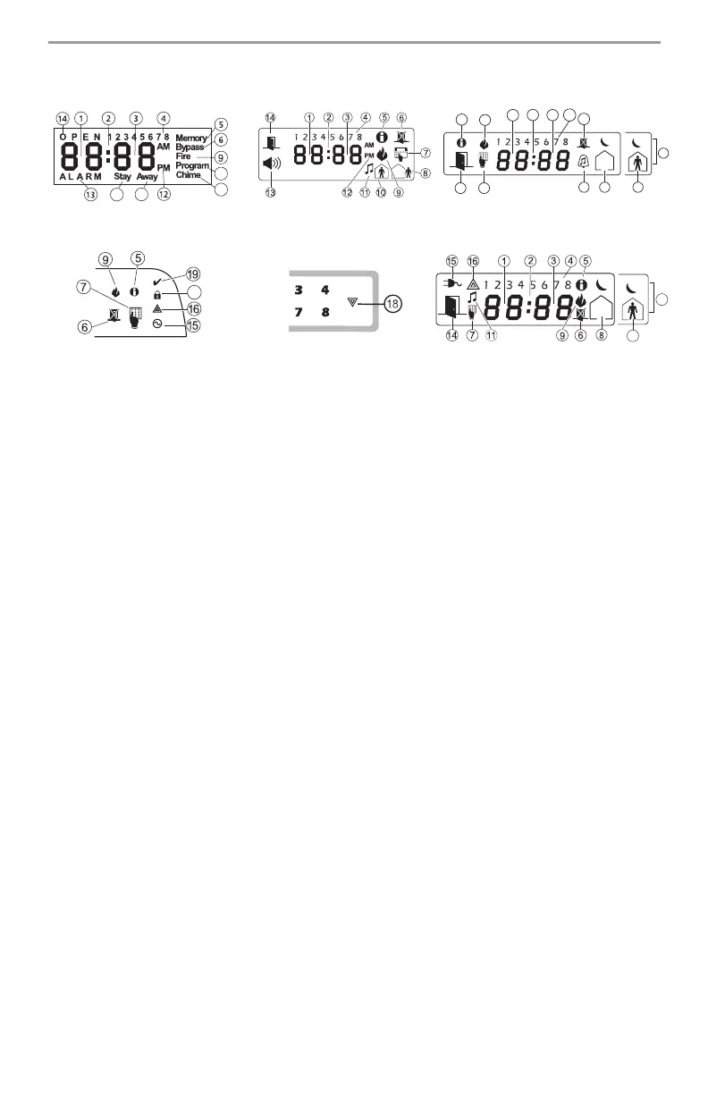
Keypad Display Symbols
810
7
11
20
5
9
6
14 7
10
11
1
8
17
2
3
4
LCD5501 Fixed Message
LCD5501 ICON
LED5511
PK5508/5516/RFK5508/5516
PK5501/RFK5501
10
17
LCD5511
1 Clock Digits 1, 2 – These two 7 segment clock digits indicate the hour digits when the local
clock is active, and identify the zone when the OPEN or ALARM icons are active. These two dig-
its scroll one zone per second from the lowest zone number to the highest when scrolling
through
zones.
2 : (Colon) –
This
icon
is
the hours/minutes divider and will flash once a second when the local
clock is active.
3 Clock Digits 3, 4 –
These
two
7
segment displays are the minute digits when the local clock is
active.
4
1to8– These numbers identify troubles when [][2] is pressed.
5 Memory –
Indicates
that
there
are alarms in memory.
6 Bypass – Indicates that there are zones automatically or manually bypassed.
7 Program – indicates that the system is in Installer’s Programming, or the keypad is busy.
8 Away – Indicates that the panel is armed in the Away Mode.
9 Fire – Indicates that there are fire alarms in memory.
10 Stay – Indicates that the panel is armed in the Stay Mode.
11
Chime – This icon turns on when the Chime function key is
pressed to enable Door Chime on
the system. It will turn off when the chime function key is pressed again to disable Door Chime.
12 AM, PM – This icon indicates that the local clock is displaying 12 Hr. time. These icons will not
be on if
the system is programmed for 24 Hr. time.
13 ALARM –
This icon is used with clock digits 1 and 2 to indicate zones in alarm on the system.
When
a
zone
is in alarm, the ALARM icon will turn on, and 7 segment displays 1 and 2 will
scroll through the zones in alarm.
14 OPEN –
This icon is used with clock digits 1 and 2 to indicate violated zones (not alarm) on the
system. When zones are opened, the OPEN icon will turn on, and 7 segment displays 1 and 2
will scroll through the violated zones.
15 AC –
Indicates that AC is present at the main panel.
16 System Trouble – Indicates that a system trouble is active.
17 Night – Indicates that the panel is armed in the Night Mode.
18 System - Indicates one or more of the following:
Memory –
Indicates
that
there
are alarms in memory.
Bypass –
Indicates that there are zones automatically or manually bypassed.
System
Trouble –
This
icon
is displayed when a system trouble is active.
19 Ready Light (green) – If the Ready light is on, the system is ready for arming.
20 Armed Light (red) – If the Armed light is on, the system has been armed successfully.