4
S E T U P & W I R I N G
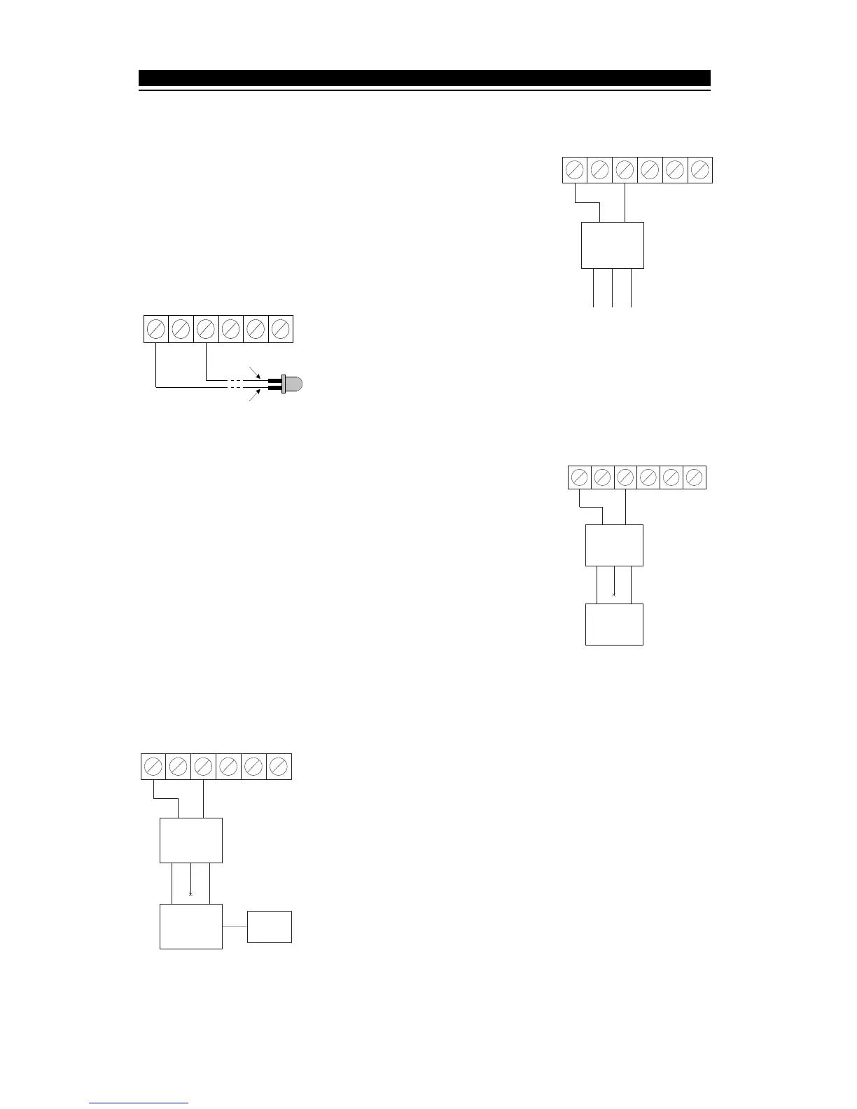
2.6 RF5108-433 Programmable Outputs - PGM1 and PGM2
Each PGM output is an open collector switch to ground. That is,
when the PGM output is activated the terminal will switch to
ground. PGM1 and PGM2 are able to sink up to 50mA of current.
If more than 50mA of current is required a relay must be used.
Refer to diagram at right.
NOTE: The current used from PGM outputs should be taken
in consideration when using the maximum current available at
the AUX output in the control panel.
2.7 Connecting LED to
the RF5108-433
The LED can be used to indicate whether the system is armed
or disarmed. If the output is programmed as an armed status
output, the red LED will turn on when the system is armed and
will turn off when the system is disarmed.
2.8 Connecting a Garage Door to the RF5108-433
Connect an output of the RF5108-433 across the wall-mounted
push button or directly at the motor of the garage door opener
(please consult the garage door opener instructions for proper
connections). Set up the system and wireless key so that it is
programmed to pulse an output for a short duration (5 seconds)
so that every time the programmed key is pressed the garage
door is opened or closed. The system can also be set up so that
an output on the RF5108-433 will follow a main panel output that
is programmed as a command output and is set up on the
wireless key as such. Doing this will also activate an output on the
RF5108-433 for 5 seconds (please refer to the control panel
manual for a listing of available output types and their functions).
PGM 1 and/or PGM 2 on the RF5108-433 can be set up to open a garage door (refer to
Section 3.5). NOTE: Not to be used in UL Listed installations.
2.9 Connecting an X-10 Powerflash Module to the RF5108-433
When connecting an X-10 Powerflash module to the RF5108-
433, different lights within or outside the home can be controlled,
such as table lamps, or porch and driveway lights that illuminate
the entry / exit paths. This can be done by setting up the system
and wireless key in one of several ways:
• The wireless key can toggle an output ON/OFF, triggering the
X-10 Powerflash module, providing direct control of lighting.
• The wireless key can turn on an output for a programmable
amount of time (5 seconds to 99 minutes and 99 seconds),
turning on lights for the amount of time the homeowner requires.
• The RF5108 output can be programmed to follow a main panel
output which can turn on lights when the panel is armed and turn them off when
disarmed, turn on lights when an alarm occurs and turn them off when disarmed, etc.
PGM1 GRNYELBLKREDPGM2
DSC
RM-1/
RM-1C
RED
BLK
WHT (COM)
YEL (NC)
GRN (NO)
PGM1 GRNYELBLKREDPGM2
RED
BLACK
PGM1 GRNYELBLKREDPGM2
RED
BLK
WHT (COM)
YEL (NC)
GRN (NO)
Garage door
pushbutton
or motor
DSC
RM-1/
RM-1C
PGM1 GRNYELBLKREDPGM2
RED
BLK
WHT (COM)
YEL (NC)
GRN (NO)
X-10
Powerflash
Module
Lamp
Module
DSC
RM-1/
RM-1C