Item Description
1 External Antenna Screw Thread
2 Brass Nut
3 Brass Washer
4 Nylon Washer (flat)
5 Antenna Mounting Tab
6 Nylon Washer with bushing (thicker flat washer)
7 Antenna Cable
8 Mounting Holes
9 Mounting Plate
10 Communicator Board
11 Stand Off
2.
Install the Communicator into the panel:
a.
Attach one end of the PC-LINK cable to the panel PCLINK_2 header on the panel (red wire goes on the right-
hand pin of the panelPCLINK_2 header (see Figure 3)).
b. Insert the assembled communicator into the panel.
NOTE: Ensure that the threaded antenna connection point is visible through the knockout hole at the top right of
the panel.
c. Place the nylon washer with bushing (thickflat washer) onto the threaded section of the antenna cable. Insert the
threaded section through the antenna mounting knockout hole at top right of panel.
d. Place the second nylon washer (flat), followed by the brasswasher and the brassnut, onto the threaded section
of the cable, outside the panel. Tighten the assembly by hand only (finger tight only- do not over tighten the
antenna assembly).
e.
Locate the screw hole on the right side wall of the panel. See Figure 2 "screw". Line up the assembled com-
municator with the right side wall of the panel and, using the screw provided, secure the mounting bracket to the
panel.
f.
Attach the other end of the PC-LINK cable to the communicator (red wire goes on the right-hand pin of the com-
municator PC-LINK header (See Figure 3)).
g. Using light pressure (finger tight only), attach the supplied white quad band whip antenna to the threaded
antenna connection point at top of the panel.
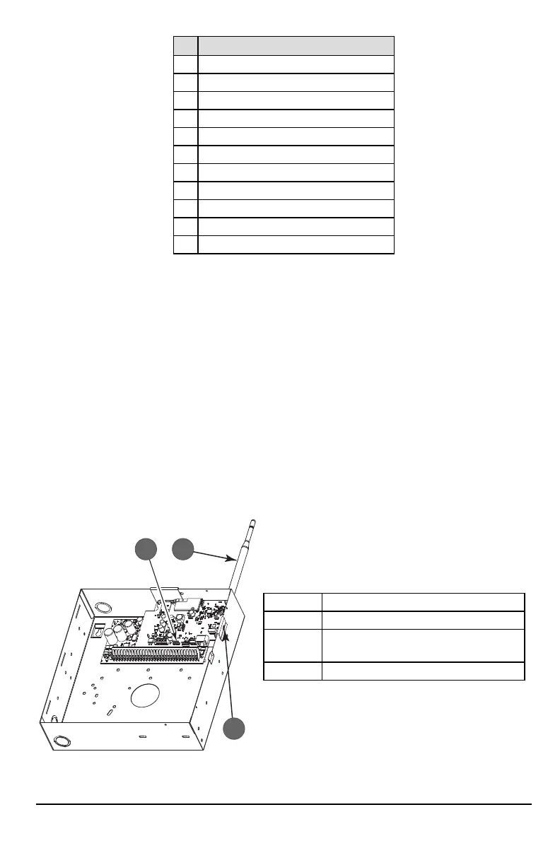
Figure 2: HS2016/2016-4/2032/2064/2128 Control Panel
Item Description
1 PC-Link Cable Connector
2
Quad Band Whip Antenna - Use light pressure to
attach antenna finger tight only
3 Screw
WARNING! - 3G2080(R)E/TL2803G(R)E/LE2080(R)/TL280LE(R) modules are power limited. Donot route any wiring
over the circuit board. Maintainat least 1in. (25.4mm) separation between circuit boardand wiring. A minimum of ¼
in. (7mm) separation must be maintained at all points between non-power limited wiring and power limited wiring.
8