2.10.9 DSENET
®
(EXPANSION MODULES)
NOTE: For further details of module configuration, refer to DSE Publication: 057-238
DSE8610 MKII Configuration Suite PC Software Manual.
NOTE: As a termination resistor is internally fitted to the controller, the controller must be
the ‘first’ unit on the DSENet
®
link. A termination resistor MUST be fitted to the ‘last’ unit on
the DSENet
®
link. For connection details, refer to section entitled Typical Arrangement of
DSENet
®
elsewhere in this document.
NOTE: DSE recommend Belden 9841 (or equivalent) cable for DSENet
®
communication.
This is rated to a maximum cable length of 1.2 km. DSE Stock Belden 9841 cable, DSE Part
Number: 016-030.
DSENet
®
is the interconnection cable between the host controller and the expansion module(s) and
must not be connected to any device other than DSE equipment designed for connection to the
DSENet
®
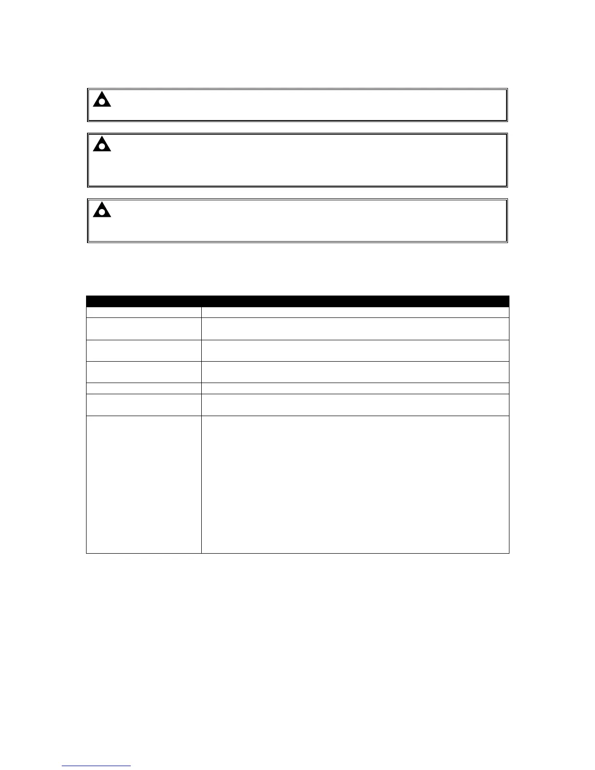
Cable Type Two core screened and shielded twisted pair
Cable Characteristics
120 Ω
Low capacitance
Recommended Cable
Belden 9841
Belden 9271
Maximum Cable Length
1200 m (¾ mile) when using Belden 9841 or direct equivalent.
600 m (656 yards) when using Belden 9271 or direct equivalent.
DSENet
®
Topology “Daisy Chain” Bus with no stubs (spurs)
DSENet
®
Termination
120 Ω. Fitted internally to host controller. Must be fitted externally to the
‘last’ expansion module.
Maximum Expansion
Modules
Total 20 devices made up of DSE2130 (up to 4), DSE2131 (up to 4),
DSE2133 (up to 4), DSE2152 (up to 4), DSE2157 (up to 10), DSE2548
(up to 10)
This gives the possibility of :
Maximum 32 additional 0-10 V or 4-20 mA outputs (DSE2152)
Maximum 80 additional relay outputs (DSE2157)
Maximum 80 additional LED indicators
Maximum 24 additional RTD or thermocouple inputs (DSE2133).
Maximum 32 additional inputs (Can be configured as either digital, or
resistive when using DSE2130)
Maximum 40 additional flexible inputs (All can be configured as either
digital, resistive, 0-10 V or 4-20 mA when using DSE2131)

 Loading...