■■■■■■■■■■■■■■■■■■■■■■■■■■■■■■■■■■■■■■■■■■■■■■■■■■■■■■■■■■■■■■■■■■■■■■■■■■■■
▼
Signal Connection to External Devices
DS1104 Hardware Installation and Configuration March 2004
135
▲
■■■■■■■■■■I
▲■■■■■■■■■■■■■■■
Encoder without
index signal
You can leave the IDX and IDX pins unconnected if your encoder does
not provide an index signal. In this case, you cannot use RTLib
functions or RTI blocks that require an index signal.
Supplying Power to Encoders
Using VCC pins The DS1104 offers two VCC pins. You should use these supply
voltages for all connected incremental encoders.
Connect both pins so that the current is shared evenly by both pins.
Use wires of sufficient diameter to avoid voltage drops.
The total load of all connector pins that provide access to the PC
power supply must not exceed 500 mA (DS1104 or via CP1104) or
400 mA (CLP1104).
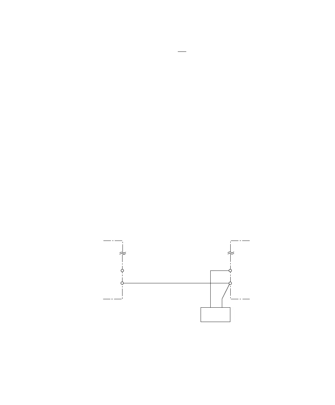
Using an external
power supply
If you use an external supply voltage, you have:
■ To guarantee that no input voltages are fed to the DS1104 while it
is switched off
■ To connect the encoder’s ground line to a ground pin of the board
(see example below)
Incremental encoder
output
DS1104
GND
External
VSupply
VSupply
GND
VCC