19
5. Ifnotpreviouslydone,removeknockoutsforACInputandACOutputinthetopoftheLSNinvertersystem(See
Figure1inSection104.1).
CAUTION: Donotdrillthecabinet;drilllingsmaydamagetheunitandpreventitfromoperating.Iflarger
knockouts are needed, use a chassis punch to enlarge the appropriate knockout. Do not add additional or
unnecessary knockouts.
IfplanningtoconnectacomputerorterminaltotheLSNinvertersystemunit’sRS232port,removeoneofthe
knockoutsinthetopoftheunitatthistime(SeeFigure1inSection104.1).Ifnecessary,enlargetheknockout;it
shouldbeabletoacceptatleast1.25-inch(32mm)conduit.
6. Install the input and output conduit.
7. IMPORTANT: Run the AC Input service conductors and AC Output conductors through separate conduits.
Emergency output conductors and non-emergency output conductors must also be run through separate conduits.
LSN inverter system emergency output circuits shall be installed in dedicated conduit systems and not shared with
otherelectricalcircuitsasdescribedinNEC700-9(b).
106.2 AC Input and AC Output Connections
Make all AC input and output connections to the LSN inverter system as indicated on labels within the cabinet. If
system was supplied with internal output circuit breaker distribution option, remove circuit breaker distribution cover
and make wiring connections directly to the circuit breakers and re-install cover.
If the LSN system is to incorporate a bypass switch, it is recommended that the "Phase Check Procedure" as
described in Section 109 be performed - wiring instructions are supplied with the bypass switch.
IMPORTANT:Tomakesurephasingiscorrect,makeallterminalstripconnectionsexactlyastheyarelabeled.Good
ground connections are necessary to reduce electrical noise and ensure safe operation of the LSN inverter system
unit and the loads.
CAUTION:
• Before installing the bypass switch, turn off the unit's AC input power at the service panel and turn off the
bypass switch and AC disconnect switch to prevent electrical shock or equipment damage.
• Before operating the bypass switch after installation, perform the Phase Check in Section 109.
• DO NOT change the external bypass switch’s position from UPS to Line or Line to UPS when line is present
and:
1) the UPS output is shut off or
2) the UPS is running on battery power.
!
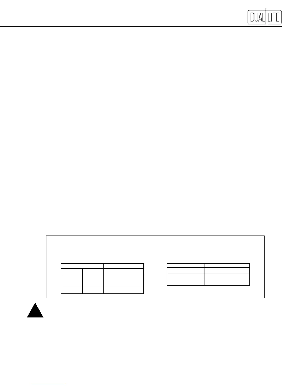
Caution: Torque all connections in accordance with the following tables.
Failure to do so may create an unsafe condition or fire hazard.
"C" Breakers
Rating Torque
amps inch-lbs.
10-60 25
80 34
Terminals
Terminal Width Torque
Inches mm inch-lbs.
31/64 12.2 16
19/32 15.2 32
25/32 20 64