48
9 - START UP PROCEDURE
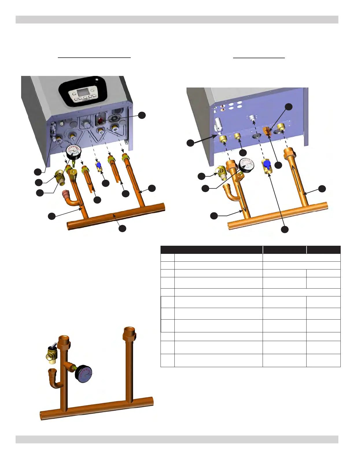
9.2 Central Heating System Connections - Combi
DCC-115 & 150 COMBI
DCC-205 COMBI
LEGEND 115 & 150 205
A Pressure Gauge -
B Pressure Relief Valve 30.00 psi [2.11 bar]
C Heating return connection 3/4" [22.2 mm] 1" [25.4 mm]
D
for Combi
1/2"
[15.9 mm]
3/4" NPT
E 3/4" [22.2 mm]
F Boiler Fast Fill External to Boiler NA
G DHW outlet/indirect storage tank connection
1/2"
[15.9 mm]
3/4" NPT
H Drain connection for condensate
13/16" [21 mm] ID
Hose
3/4 NPT
I Heating supply connection 3/4" [22.2 mm] 1" [25.4 mm]
J Manifold 1-1/4" (6.35 mm) NA
K
(Factory installed) (205 only)
na
3/4"
[22.2 mm]
A
B
H
I
E
C
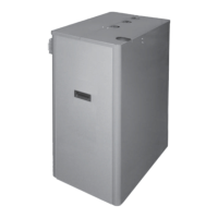
MANIFOLD
DCC-115, 150 & 205
K
G
D
A
D
C
F
G
E
I
B
H
J
240013360
REV A [07/01/2021]