42
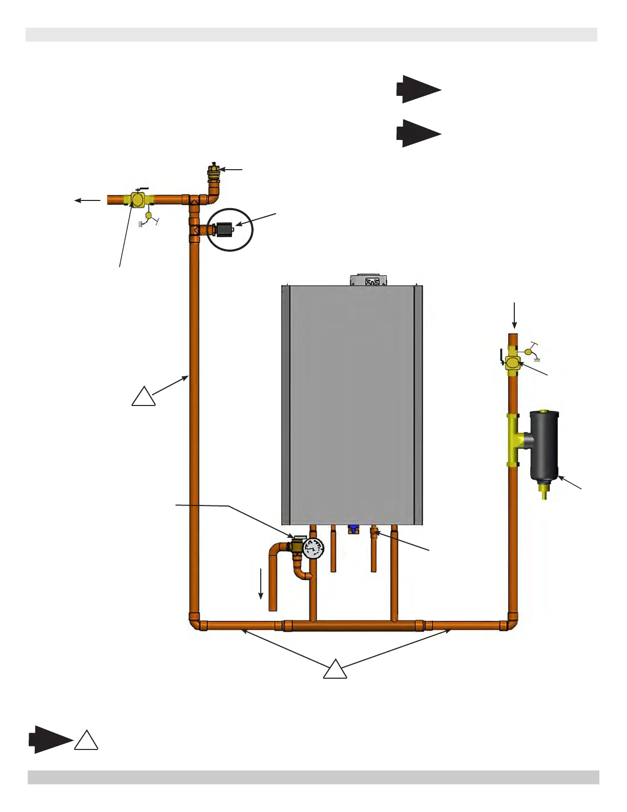
Piping Diagram - LWCO Location
LOW WATER CUTOFF
Air Vent
Supply
Gas
Boiler
Safety Relief
Valve
Position LWCO Above
Top of Boiler
1
DO NOT PLACE ISOLATION VALVE
BEFORE TEE OR LWCO.
Note
1
*To Drain
* Check Local Codes for
Maximum Distance to
Floor.
Arrange piping to prevent water
dripping onto boiler.
1
Return
5 gpm Limiter
Factory Installed
205 Only
Magnetic
Dirt
Separator
Purge Valve
Purge Valve
Note
Illustrations are meant to show
system piping concept only. Installer
is responsible for all equipment and
detailing required by authority having
jurisdiction.
Note
PN 240011430 REV. O [07/01/2021]