24
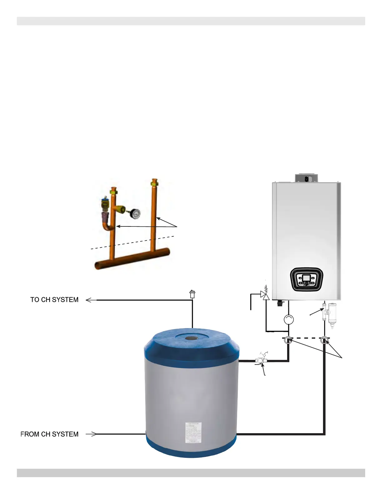
EXTERNAL BUFFER TANK - PIPING DIAGRAM
Note:
• DHW piping not shown for clarity. Reference applicable sections of this
manual for DHW piping details.
• Internal Boiler circulator used on Primary circuit.
Buffer Tank on Central Heat Circuit Using Internal Boiler Circulator
Buffer Tank Piping
When installing low mass systems, additional water mass
may be required to avoid short cycling by the boiler. In
these applications it is recommended that a buffer tank be
installed.
H2O Stainless
Steel Buffer
Tank
MAGNETIC
DIRT
SEPARATOR
PURGE
VALVE
Cut Manifold
Use Stubs To
Connect To Boiler
Increase
Pipe Size
to Match
Buffer Tank
Connections
PN 240011430 REV. O [07/01/2021]