45
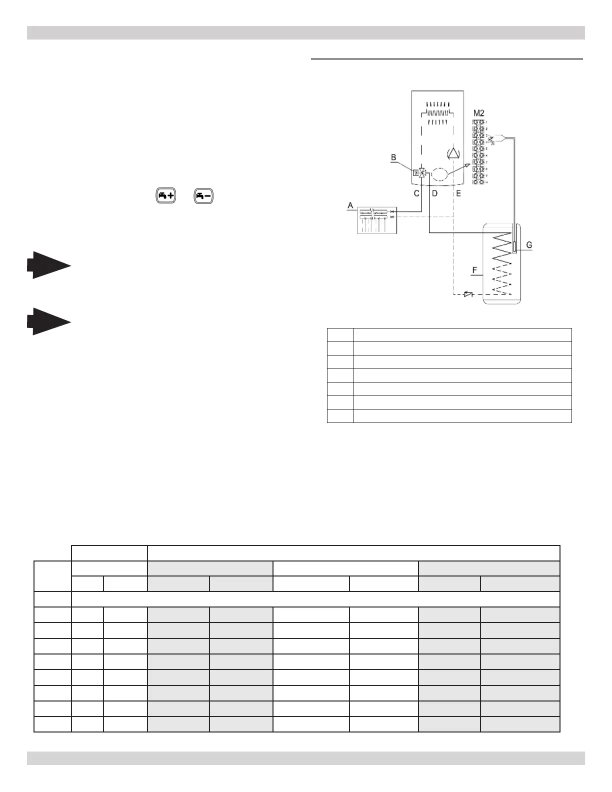
8.8 Indirect Storage Tank
A Heating system
B Three way diverter valve
C
D Heating supply to DHW indirect storage tank coil
E Heating water return
F Tank
G
Boilers DCB-100 & DCB-125 can be electrically connected to
indirect storage tank as follows:
• Connect DHW priority 10K Ω sensor NTC to terminals 3-4
on terminal block M2.
• Insert 10K Ω NTC sensor element in the sensor well of
indirect storage tank.
• Verify exchange capacity of the storage boiler coil is
appropriate for boiler power.
• Adjust DHW temperature +95 °F...+140 °F (+35
°C...+60 °C) by pressing
or on boiler Control.
IMPORTANT: set parameter P03 = 05 as described in:
"PARAMETER SETTINGS".
8 - ELECTRICAL CONNECTIONS
FIGURE 8-7 Kt Indirect Storage Tank
*125 Model shown - See Application Guide for size 100
Note
Sensors used for this boiler are proprietary to
the manufacturer. Use of after market sensors
will diminish boiler performance.
10K Ω Sensor
8.9 Management of 0-10V Input
The functions with 0...10V regulator are activated by means of their parameters:
To enable 0-10V input change P82=4 to P82=3,
When P78=1 the input manages the heating set point temperature directly.
When P78=2 the input manages the heating power input directly.
Demand is activated above 3V and heating setpoint is calculated in proportion to deviation from 3 to 10 V DC, to give a
setpoint that goes from minimum to maximum.
Terminal # 9 is negative (-), terminal #10 is positive (+).
P78=1 P78 = 2
Voltage Temp Setting 100/115 125/150 165/205
°C °F kW MBH kW MBH kW MBH
0-3 OFF
3 25 77 4.9 16.6 6.4 22.0 8.6 29.5
4 32 90 8.4 28.9 10.7 36.5 14.4 49.0
5 40 104 12.0 40.8 14.9 51.0 19.9 68.0
6 49 120 15.4 52.4 19.2 65.5 25.5 87.0
7 57 135 18.5 63.1 23.4 80.0 31.1 106.0
8 65 149 22.2 75.7 27.7 94.5 36.6 125.0
9 73 163 25.3 86.2 31.9 109.0 42.5 145.0
10 80 176 27.4 93.6 36.9 125.0 48.1 164.0
Note
Model 165 Use aquastat for Indirect Tank
Control.
240013360
REV A [07/01/2021]