53
9.12 Chimney Sweep Function
For correct boiler operation, content of (CO2 - O2
Combustion
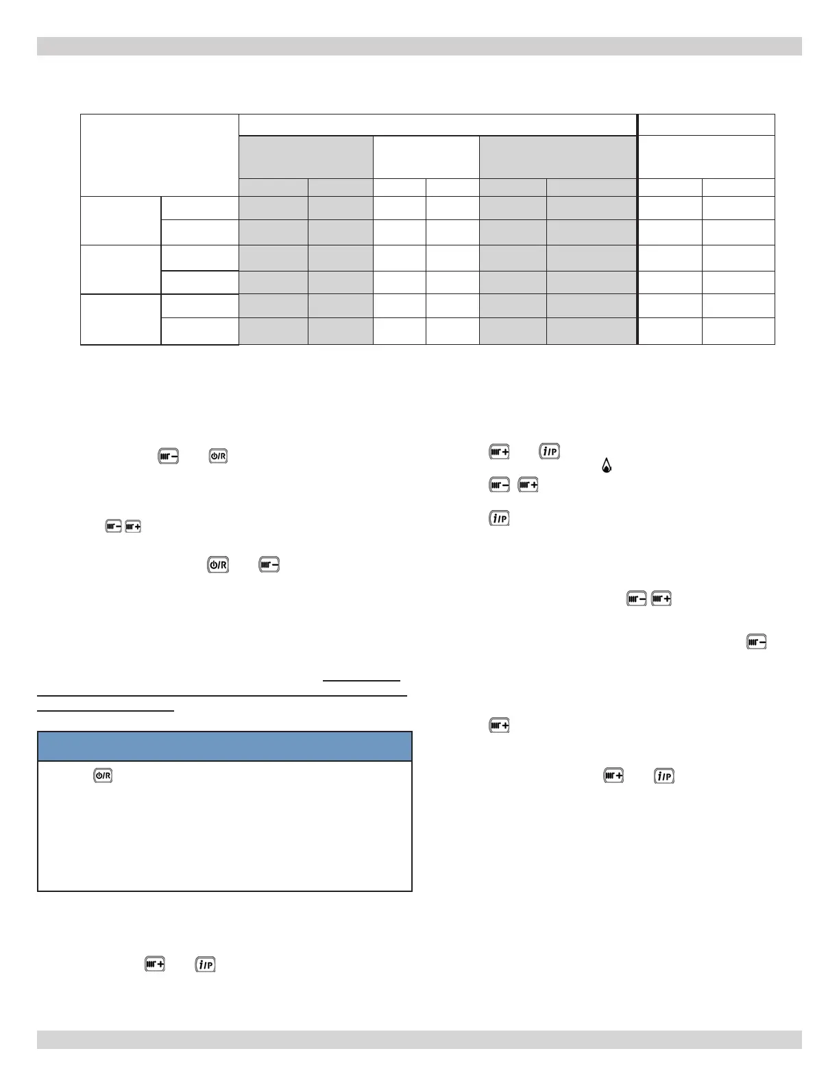
Table
Gas A (Natural Gas) Gas E (LPG)
DCB-100
DCC-115 & 150
DCB-125
DCB-165
DCC-205
All
CO2 %
O2 %
CO2 % O2 % CO2 % O2 % CO2 % O2 %
Maximum
Power
(100%)
Nominal value
9.0
4.9 8.7 5.4 9.0 4.9 10.0 5.7
Permitted
value
8.5 – 9.5 4.0 – 5.7 8.2 – 9.3 4.3 – 6.3 8.5 – 9.5 4.0 – 5.7 9.5 – 10.5 4.9 – 6.4
Ignition
power (*)
Nominal value
8.7 5.4 8.7 5.4 8.7 5.4 10.8 4.8
Permitted
value
8.2 – 9.3 4.3 – 6.3 8.2 – 9.3 4.3 – 6.3 8.2 – 9.3 4.3 – 6.3 10.3 – 11.3 3.7 – 5.2
Minimum
power (0%)
Nominal value
8.8 5.2 8.8 5.2 9.0 4.9 9.8 6.0
Permitted
value
8.2 – 9.3 4.6 – 6.3 8.2 – 9.3 4.3 – 6.3 8.5 – 9.5 4.0 – 5.7 9.3 – 10.3 5.2 – 6.7
Chimney Sweep Function enables boiler to generate maximum
heating power.
After activation, boiler power % can be adjusted from
minimum (0%) to maximum (100%) in DHW mode.
A. Press and hold and at the same time for 6
seconds. When the function is enabled, displays shows
“On” for few seconds followed by program row “303”
alternating with % of boiler power.
B. Press to gradually adjust power (increments of
1%).
C. To exit press and hold, and power/reset buttons,
for at least 6 seconds.
D. If value of CO
2
-O2
their relative distances. See Figure 11-1.
If necessary, replace electrodes and position them correctly.
If problem persists, use "COMBUSTION ADJUSTMENT
FUNCTION (CO
2
%)". See Section 11 General Maintenance,
Figure 11-1 Electrodes. If problem persists, use Section 9.8
Automatic Calibration Function, and Section 9.9 Manual
Calibration Function.
NOTICE
• Press
15 seconds.
• Use a regularly calibrated combustion analyzer for
combustion analysis.
• During normal operation boiler performs combustion
control cycles. In this phase CO values higher than 400
ppm can occur for brief periods of time.
9 - START UP PROCEDURE
(*) Automatically calculated from the PCB
9.14 Check Firing Rate
1.
Measure input, if a gas meter is installed in the system.
•
• Activate some heating zones to dissipate heat.
•
• Use ½, 1 or 2 cu ft dial on gas meter. Measure time
required for two or more complete revolutions. Measure
time
for one or more minutes.
• Calculate input.
9.13 Combustion Adjustment Function (CO2%)
This function sets out to partially adjust the value of CO
2
%.
Use the following procedure:
1.
Press buttons and together for at least 6 seconds.
When the function is enabled, displays shows “On” for a
few seconds followed by program row “304” alternated
with the % of boiler power;
2.
After burner is lit, boiler reverts to maximum DHW power
(100). When display shows "100" it is possible to partially
adjust value of CO
2
%;
3.
Press and . Display shows "00" alternating with
function number "304" (
4.
Press to raise or lower the amount of CO
2
(from
-0.3% to + 0.3%);
5.
Press to save new value. Power value "100" will show
on display again. Boiler continues operating at maximum
DHW power.
This procedure can be used to adjust CO
2
to ignition power
and minimum power by pressing
after performing step
5 above.
6.
After saving the new value (step 5 above), press
to set boiler to ignition power. Wait for value of CO
2
to stabilize. Adjust as described in step 4 of procedure
(power value is a number <> 100 and <> 0). Repeat step
5 to save.
7.
Press to adjust boiler to minimum power. Wait for
value of CO
2
to stabilize. Go to step 4 to adjust (power
value = 00);
8.
Exit function by pressing and together for at least
6 seconds, see step 1.
240013360
REV A [07/01/2021]