22
5 - COMBUSTION AIR AND VENT PIPING
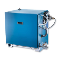
FIGURE 5-4 Roof Mount Coaxial Venting
CAN BE USED ON ALL SIZES
Maintain 12"(305 mm)
US (18"(457 mm)
Canada) clearance
above highest
anticipated snow level
24" (610 mm) above
roof or ground
Anticipated
Snow Line
FIGURE 5-6 Side Wall Coaxial Venting
CAN BE USED ON ALL SIZES
Min. 8" (181 mm)
Max. 14" (356 mm)
Maintain 12"(305 mm)
US (18"(457 mm)
Canada) clearance
above highest
anticipated snow level
24" (610 mm) above
roof or ground
Ground
Anticipated
Snow Line
18" Vertical
Clearance to
FIGURE 5-5 - Coaxial Vertical Exhaust -
CAN BE USED ON ALL SIZES
12" (305 mm)
Minimum Separation
Manufacturer
Recommends
Greater Separation
FIGURE 5-7 - Coaxial Horizontal Exhaust -
CAN BE USED ON ALL SIZES
Multiple
Appliances
Multiple
Appliances
24" (610 mm)
Min. Separation
Manufacturer
Recommends
Greater Separation
recommends gr
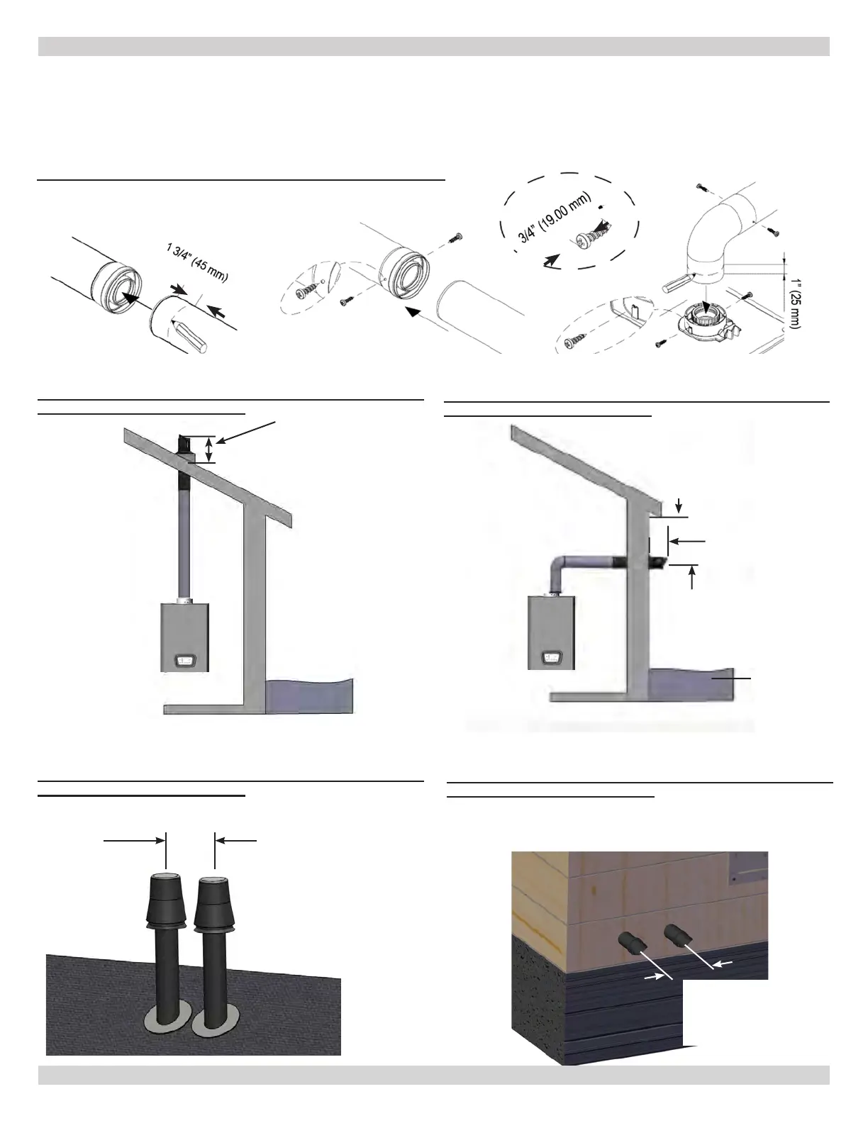
5.7 Coaxial Vent Screw Placement - See Figure 5-2
Two (2) screws shall be fastened through the outer intake pipe
behind the gaskets at equal distances, approximately 180°
apart. Note the screws used must be no larger than No. 8-3/4
sheet metal screws and must be zinc coated.
Figure 5-2 - Coaxial Screw Placement
1-3/4" (45mm)
3/4" (19mm)
240013360
REV A [07/01/2021]