30
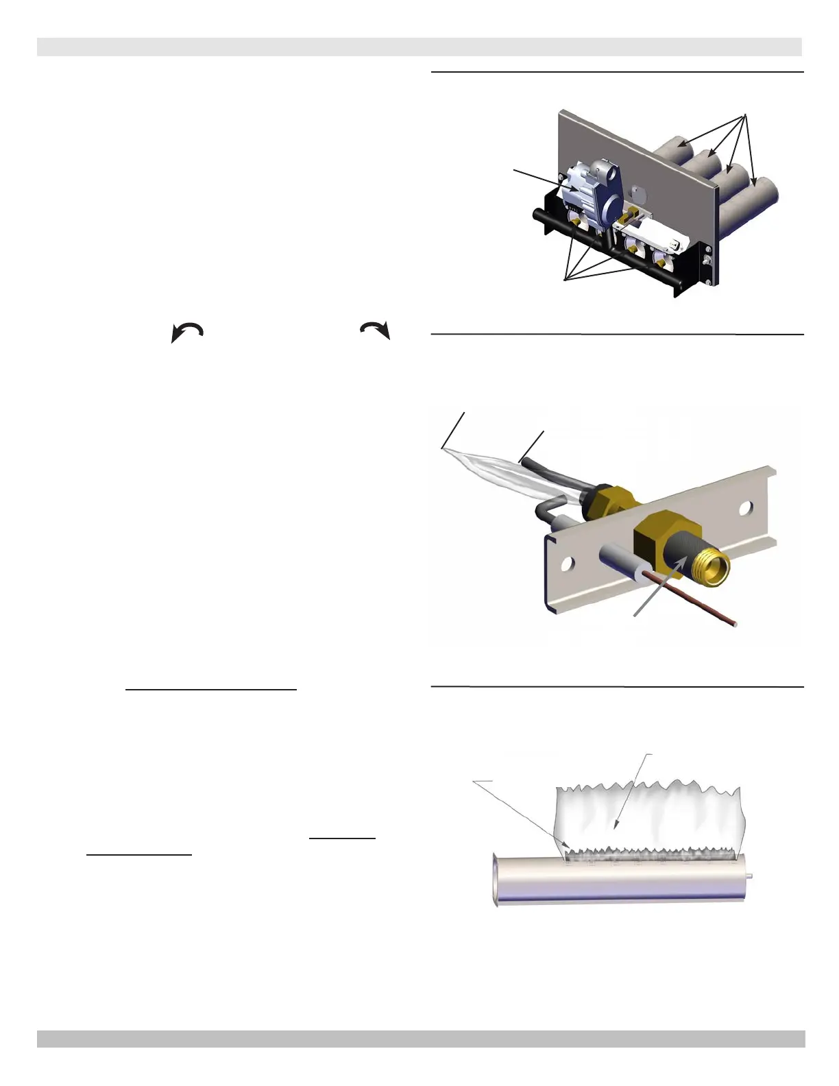
Figure 14-3 - Gas Burner Flame
Figure 14-2 - Gas Burner Pilot Assembly
Figure 14-1 - Burner Tray
BURNERS
ORIFICES
GAS VALVE
•
heating season and again in mid-season.
blue mantel with lighter blue outer mantel.
dust obstruction.
Figures 14-1 and 14-3.
•
ignition/sensing electrode. See
Figure 14-2.
•
cover screw and turn inner adjustment screw
counterclockwise
to increase or clockwise
adjustment to prevent possible gas leakage. See
Figure 12-1, Page 27.
• Check burners and pilot for signs of corrosion, rust or
scale buildup.
• Area around boiler shall be clear and free of
vapors and liquids.
•
boiler room shall not be restricted or blocked.
•
per manufacturer's instructions.
• Contact a Qualied Service Agency to make
annual inspection of boiler and heating system.
This should include:
1.
Check casting and vent for signs of corrosion from
condensate.
2.
Examine pilot lint screen and clean if needed.
3.
Check venting for any signs of corrosion, rust,
damage or deterioration. Contact a Qualied
Service Agency immediately if you observe any of
these conditions.
4.
abrasive cloth.
14.3 General Maintenance
14 - GENERAL MAINTENANCE AND CARE INSTRUCTIONS
INNER BLUE
MANTEL
LIGHT BLUE
OUTER MANTEL
3/8" to 1/2 "
(9.5 to 12.7mm)
PILOT LINT
SCREEN
Proper Flame
Adjustment
Shown
PN 240012787 Rev. C [11/15/2020]