35
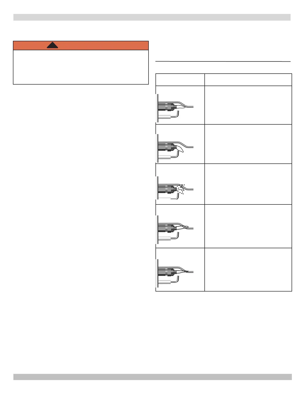
APPEARANCE CAUSE
SMALL BLUE FLAME
CHECK FOR LACK OF GAS FROM:
• CLOGGED ORIFICE FILTER
• CLOGGED PILOT FILTER
• LOW GAS SUPPLY PRESSURE
• PILOT ADJUSTMENT AT MINIMUM
LAZY YELLOW FLAME
CHECK FOR LACK OF AIR FROM:
• DIRTY ORIFICE
• DIRTY LINT SCREEN, IF USED
• DIRTY PRIMARY AIR OPENING IF THERE
IS ONE
• PILOT ADJUSTMENT AT MINIMUM
WAVY BLUE FLAME
CHECK FOR:
• EXCESSIVE DRAFT AT PILOT LOCATION
• RECIRCULATING PRODUCTS OF
COMBUSTION
NOISY LIFTING
BLOWING FLAME
CHECK FOR:
• HIGH GAS PRESSURE
HARD SHARP FLAME
THIS FLAME IS CHARACTERISTIC OF
MANUFACTURED GAS
CHECK FOR:
• HIGH GAS PRESSURE
• ORIFICE TOO SMALL
Figure A-1 - Troubleshooting Pilot Flame
STEP 3: Check spark ignition circuit.
WARNING
Electrical shock hazard. Ignition circuit generates
over 10,000 volts. Turn OFF electrical power
supply at service panel before making electrical
connections. Failure to do so could result in death
or serious injury.
!
Energize module and listen for audible sparking noise.
When operating normally, there should be a buzzing noise
seconds depending on model.
Reconnect ignition cable.
STEP 4:
1.
Initiate call for heat. Turn thermostat above room
temperature. Ignition sequence may be delayed by
thermal purge up to 2 minutes.
2.
Watch pilot burner during ignition sequence.
Verify ignition spark stops within a few seconds after
pilot is lit.
Verify Main burner lights within a few seconds of
pilot lighting
a.
and causes.
b.
adjustment screw on gas control clockwise to
decrease or counterclockwise to increase pilot
assure proper gas control operation. Figure 12-1,
page 27.
3.
as follows.
Verify electrical connections are clean and tight.
Replace damaged wire.
Check for cracked ceramic insulator, which
can cause short to ground, and replace pilot if
necessary.
Set temperature below room set-point to end call for
heat.
4.
Recheck ignition sequence as follows:
a. Adjust thermostat above room temperature.
b. Verify ignition sequence at burner.
APPENDIX A - CONTROL FUNCTION
PN 240012787 Rev. C [11/15/2020]