1-25
12H-M12M0-0309-0
2-4-2. Cleaning the paper feed inlet sensor
The paper feed inlet sensor will not function if adhered with printing powder and paper dust, and an error message will
be displayed.
The LCD of the DF-920 displays “JAM FEED SECT” while the right window of the DF-915 displays “J1-2”.
When these messages appear, clean the sensor.
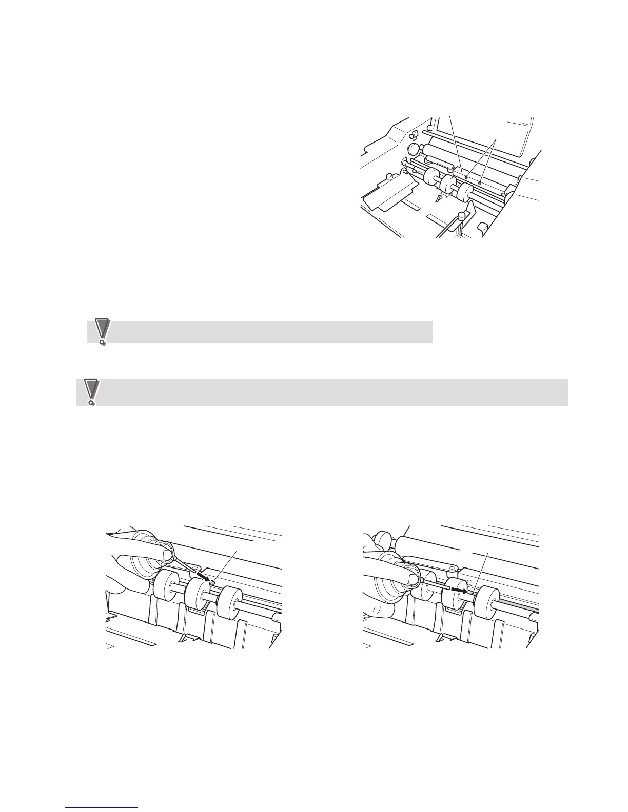
q Remove the two fixing screws, and remove the
sensor cover attached to the paper feed inlet upper
guide.
Sensor cover
Fixing screws
w Use a cloth or cotton swab to remove powder or paper dust adhered to the paper feed inlet sensor (light-emitting).
e Remove the paper feed inlet sensor (light-emitting), insert a cotton swab into the hole to remove powder or paper
dust adhered to the paper feed inlet sensor (light-receiving).
If the sensor is very dirty, remove the paper feed inlet upper guide to clean.
NoteNote
r Reinstall the paper feed inlet sensor (light-emitting) and sensor cover back to their original positions.
Be sure to perform this cleaning together with the “2-5-6. Cleaning the paper ejection outlet sensor” described
later as a set when visiting users for maintenance work.
NoteNote
2-4-3. Providing instructions on cleaning the paper feed inlet sensor to users
“21. CLEANING THE UNIT” in the instruction manual (chapter 20 in the case of the DF-915) describes the method
of cleaning using an Air Duster (a commercially available air spray for eliminating dust). Explain the details carefully to
users and instruct them on use.
With this method, the nozzle of the Air Duster is inserted into the hole of the sensor cover and paper feed inlet and
sprayed briefly.
Hole of sensor cover
Paper feed inlet
 Loading...