G2030-II-S
Apr ‘19
- 12
Maintenance Procedures (cont’d)
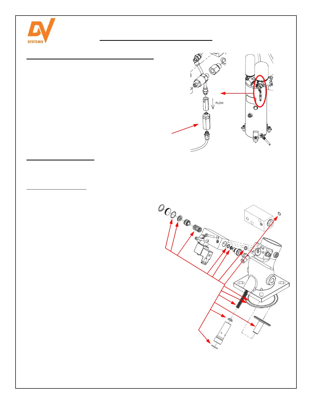
Intake Valve Repair Kit.
The Intake Valve Assembly is located directly below the Intake Filter, and opens and closes to allow air to enter
the Air End.
To repair the Intake Valve:
• Remove the Intake Filter from the top of the
Intake Valve Assembly.
• Remove the DIN Connector from the Solenoid
Valve attached to the Intake Valve Assembly.
• Remove the Intake Valve Assembly by way of
removing the (4) Screws attaching it to the Air
End
• Place a clean rag over the Air End to ensure
that nothing enters it.
• Remove the (2) Screws holding the aluminium
Manifold onto the Intake Valve.
• Remove the internal components from the
Manifold, clean the interior, and install new
components.
• Remove the Large Set Screw from the bottom
of the Intake Valve, and remove the Plunger.
• Clean the internal surfaces of the Intake Valve
and insert the new components.
• Secure the Set Screw.
• Install a new O Ring between the Manifold and
Intake Valve and secure with (2) Screws.
• Remove the rag from the Air End, install the O
Ring, and secure the Intake Valve.
• Reconnect the DIN Connector to the Solenoid,
and re-attach the Intake Filter.
Please order (1) ‘DSC-001999 Intake Valve Repair Kit.
Shown at right are the various components associated
with the Intake Valve Repair Kit.
Changing the Scavenge Line ‘In-Line’ Filter.
The ‘DSC-612’ In-Line’ Filter is located in the Scavenge
Line between the Air-Oil Separator and the Air End, and
removes any particles from the oil before it enters the Air
End. The Filter must be replaced every 4000 hours to
ensure the proper flow of oil through the Scavenge Line.
When re-assembling the parts, use Loctite thread
sealant. Do not use Teflon tape, as the tape could come
loose and obstruct the passage of oil.
In-Line Filter
 Loading...