11
5. DVC Camera Options and Special Modifications
• Electronic Shutter (1/1000 sec OR 1/2000 sec)
• Pulse Driven Integration Control
• “N” Field Integration: user specified value of “N”
• Asynchronous Reset Capability
• Genlock Option for multiple camera synchronization
• Gain & Offset Control
• Gamma Correction Options on the Analog Video Output
• Access ports for analog & digital gain/offset as well as for variable gamma control
• External Thermo-electric Cooler
• User Defined Optical Filter
• Board Level Cameras (for OEMs)
• Silicon Graphics Inc (SGI) INDY & INDIGO2 Digital Compatibility - Call DVC for an update !
• Electronically tunable (350nm to 1100nm) solid state LCD filter with fast switching for
sequential RGB and other multi-spectral applications; Call DVC for info !
• Serial Digital Video (for transmission via fiber optic, RF or twin co-ax)
5.1 TYPICAL MODE CONTROL TABLES
Some typical examples of mode control tables are shown the the next two sections. The actual
table in a particular camera depends upon the combination of options that are ordered. Note:
since the Mode Control 1 (MC1 or DB37-pin37) and the Mode Control 0 (MC0 or DB37-pin18)
are often used for the external analog video gain and offset control voltages, units that have
these external options selected are limited in the number of exposure control options that are
provided. In some cases, a special auxillary connector may be provided on the camera side
panel to increase the number of “mode control” inputs.
5.1.1 “N” Field Integration, Pulse Driven Integration & Asynchronous Reset :
DB37
- 19
DB37
-37
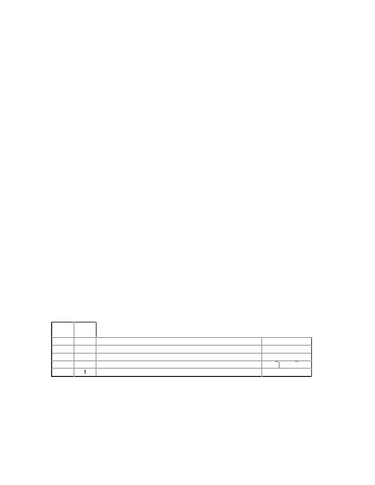
MC2 MC1 Mode Reset
0 0 Normal (Default: 1/60sec, Integ. period = 16.66ms)
↓ edge
0 1 “N” Field Integ. (N = 60); Integ. period = 1 second inactive
1 0 Pulse driven integ. (Reset LOW sets Integ. period)
¯
|____|
¯
1 1 Normal (Default: 1/60sec, Integ. period = 16.66ms)
↓ edge
Since all Mode Control (MC) and RESET pins are internally pulled up, the unit defaults to the
normal (1/60sec) mode until a pin is pulled LOW (via a computer, or by connecting it to ground).
Note: If a remote control box (with mode selection) is plugged in, the switch position
should be set to “NORMAL” before any of the Mode control pins is pulled LOW (via the
DB37 connector) by a computer or an external device other than the remote control box.


 To Next Page