25
5.8 Custom Cable Splitter (“Y” cable):
This is a custom cable (often referred to as a Y-cable or a T-cable) that is used in applications
where it is necessary to access the DB-37 connector of a DVC “DigitEyes” camera (DVC-0A,
DVC-08 or DVC-10) camera at two separate interfaces.
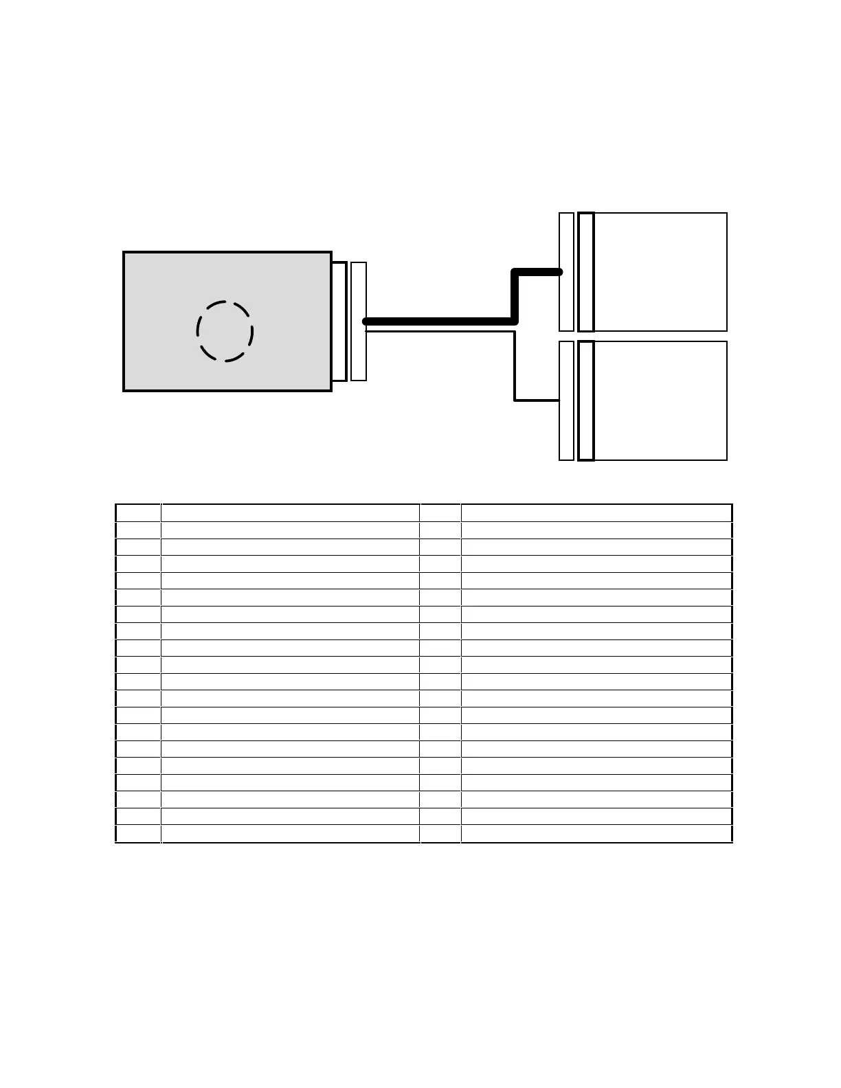
Figure 5-11
: Typical application using the Splitter
PIN SIGNAL NAME PIN SIGNAL NAME
1 PIXEL CLOCK (+) 20 PIXEL CLOCK (-)
2 LINE DATA VALID (+) 21 LINE DATA VALID (-)
3 FRAME DATA VALID (+) 22 FRAME DATA VALID (-)
4 COMPOSITE SYNC (+) 23 COMPOSITE SYNC (-)
5 FIELD INDEX (+) 24 FIELD INDEX (-)
6 VIDEO DB9 (+) (LSB FOR DVC-10) 25 VIDEO DB9 (-) (LSB FOR DVC-10)
7 VIDEO DB8 (+) 26 VIDEO DB8 (-)
8 VIDEO DB7 (+) (LSB FOR DVC-08) 27 VIDEO DB7 (-) (LSB FOR DVC-08)
9 VIDEO DB6 (+) 28 VIDEO DB6 (-)
10 VIDEO DB5 (+) 29 VIDEO DB5 (-)
11 VIDEO DB4 (+) 30 VIDEO DB4 (-)
12 VIDEO DB3 (+) 31 VIDEO DB3 (-)
13 VIDEO DB2 (+) 32 VIDEO DB2 (-)
14 VIDEO DB1 (+) 33 VIDEO DB1 (-)
15 VIDEO DB0 (+) MSB 34 VIDEO DB0 (-) MSB
16 GROUND 35 GROUND
17 RESET 36 +5VOLT AUX. POWER OUT
18 MODE CONTROL 0 (Or Offset Control) 37 MODE CONTROL 1 (Or Gain Control)
19 MODE CONTROL 2
Table 5-1
:
"Y" Cable: Pinout of ca
mera side DB-37 connector (marked "C")
The splitter connects to the female DB-37 connector (see Table 1, above) of the camera via a
male DB-37 connector from which TWO branches emerge.
(1) The Mode Control branch: consisting of the Mode Control signals, which, in the case of MC1
and MC0 may be used as the gain and offset control voltages if the ext. gain/offset option is
installed.
DVC camera
Frame grabber:
Receives CLOCK,
VIDEO_DATA &
TIMING signals;
Generates RESET
si
nal.
Remote control box:
Receives +5V & GND;
Generates Mode
Control & Gain/offset
voltages
C
D
R