43
3) Separate the optical front plate (containing the CCD sensor) from the video board gently while
keeping the board parallel to the optical front plate. Twisting the board set during this step can
bend the CCD pins and will make re-assembly quite difficult ! The CCD chip is mounted within
the optical front plate and should not be removed.
4) After the separation is complete, note the position of pin 1 of the CCD and the corresponding
pin of the socket on the video board. Pin 1 on the CCD is identified by its longer length relative
to the other pins. On the video board, a triangular mark (near the socket) identifies pin 1 of the
socket.
Note: Matching pin 1 of the CCD sensor to pin 1 of the socket on the video board is very
important during the re-assembly process.
Identify the potentiometers and switches in the camera (see next question)
8.3.12 What user adjustable controls are available within the camera?
8.3.12.1 Sync. and Power Board
There are no user adjustable controls on the sync board.
8.3.12.2 Video Board
The video board has the following controls:
• White Balance potentiometers
• Black Balance potentiometers
• Analog gain potentiometer
• Analog offset potentiometer
• Digital gain potentiometer
• Digital offset potentiometer
• Interlace level potentiometer
• Gamma select switch
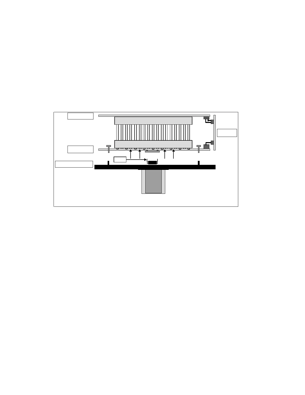
Lens
CCD
Sync board
Video board
Optical front plate
A/D board
Figure 8-1: Sketch showing Camera boards