Operating and Maintenance Instructions
EN
LC 25 – LC 40 – LC 60 – LC 106 – LC 106 Kzero – LC 151 – LC 151 Kzero – LC 205 – LC 305 – LC 205HV – LC 305HV – RC 50M
14
8702035 – 01/04/2018 – R.10 www.dvp.it
4.5 ENVIRONMENTAL CONDITIONS
The pump must be installed and used in a covered and adequately lit location. The installation area must meet all
requirements of height, air circulation and meet the requirements imposed by existing legislation.
Temperature, Humidity and altitude
The corresponding limit values are shown in the table of the technical specifications (chapter 3.3). Please contact
the Manufacturer if environmental conditions are different from those prescribed.
Lighting
All areas must be illuminated evenly and sufficiently to ensure all operations included in this manual and must be
without shadows, reflections, glare or eyestrain.
4.6 PUMP INSTALLATION
To ensure perfect pump operation, house and place it according to the following conditions:
• Allow sufficient space on the perimeter sides of the pump and make sure to keep the motor ventilation side free.
• Make sure the free space adjacent to the pump allows easy access to components for inspection or
maintenance and also allows access for suitable lifting equipment.
• The pump is equipped with mounting points. It is necessary to ensure it locks onto a perfectly horizontal plane in
order to avoid tilting in case of transportation by the system user.
• Some models are already equipped with rubber vibration dampers installed at pump attachment points.
Whenever the model has not been equipped, ensure installation of such equipment so as not to transmit
vibration to the pump.
• Ensure there is ventilation in the room, or inside the machine housing the pump and prevent air coming in from
the outlet or cooling fans, which could cause discomfort to personnel.
WARNING
Do not install the pump in any area with dust or other materials that could clog or rapidly cover
cooling surfaces.
4.7 MOTOR INSTALLATION
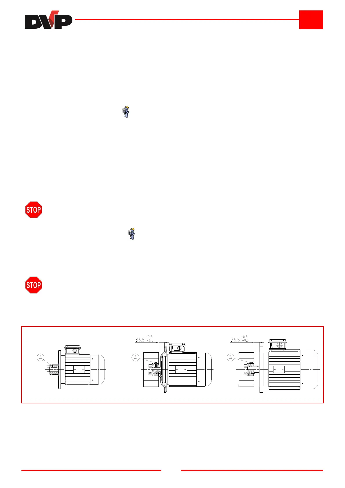
It is possible to install any type of electric or hydraulic motor (NOT for RC 50M) that has the features described in
the table of technical data, with flange and shaft corresponding to:
M100/4, M112/4 - B5 size as per standard IEC-72 for LC 106, LC 106 Kzero, LC 151 and LC 151 Kzero;
M112/4 - B14 size as per standard IEC-72 for LC 205;
M132/4 - B5 size as per standard IEC-72 for LC 205, LC 305, LC 205HV and LC 305HV.
WARNING
Install fan/coupling assembly on the motor following these instructions:
• Remove the fixing clamp from the connecting joint on the pump;
• Fit the assembly on the motor shaft up to reaching the stated measure (on the LC 106 and LC 151 models fit the
motor drive coupling up to the second shoulder);
• Tighten screw “A” to firmly fix the assembly to the shaft.
M100/4 – M112/4 M112/4 M132/4
LC 106 – LC 106 Kzero – LC 151 – LC 151 Kzero
LC 205 LC 205 – LC 305 – LC 205HV – LC 305HV
4.8 USER SYSTEM
Make sure that no harmful substances contaminate the user system during installation.
If you wish the system to maintain vacuum even when pump is stopped, install a cutoff valve between
pump and system.
Make sure that no vibrations or stresses are transmitted to the pump connection.


 To Next Page