Operating and Maintenance Instructions
EN
LC 25 – LC 40 – LC 60 – LC 106 – LC 106 Kzero – LC 151 – LC 151 Kzero – LC 205 – LC 305 – LC 205HV – LC 305HV – RC 50M
7
8702035 – 01/04/2018 – R.10 www.dvp.it
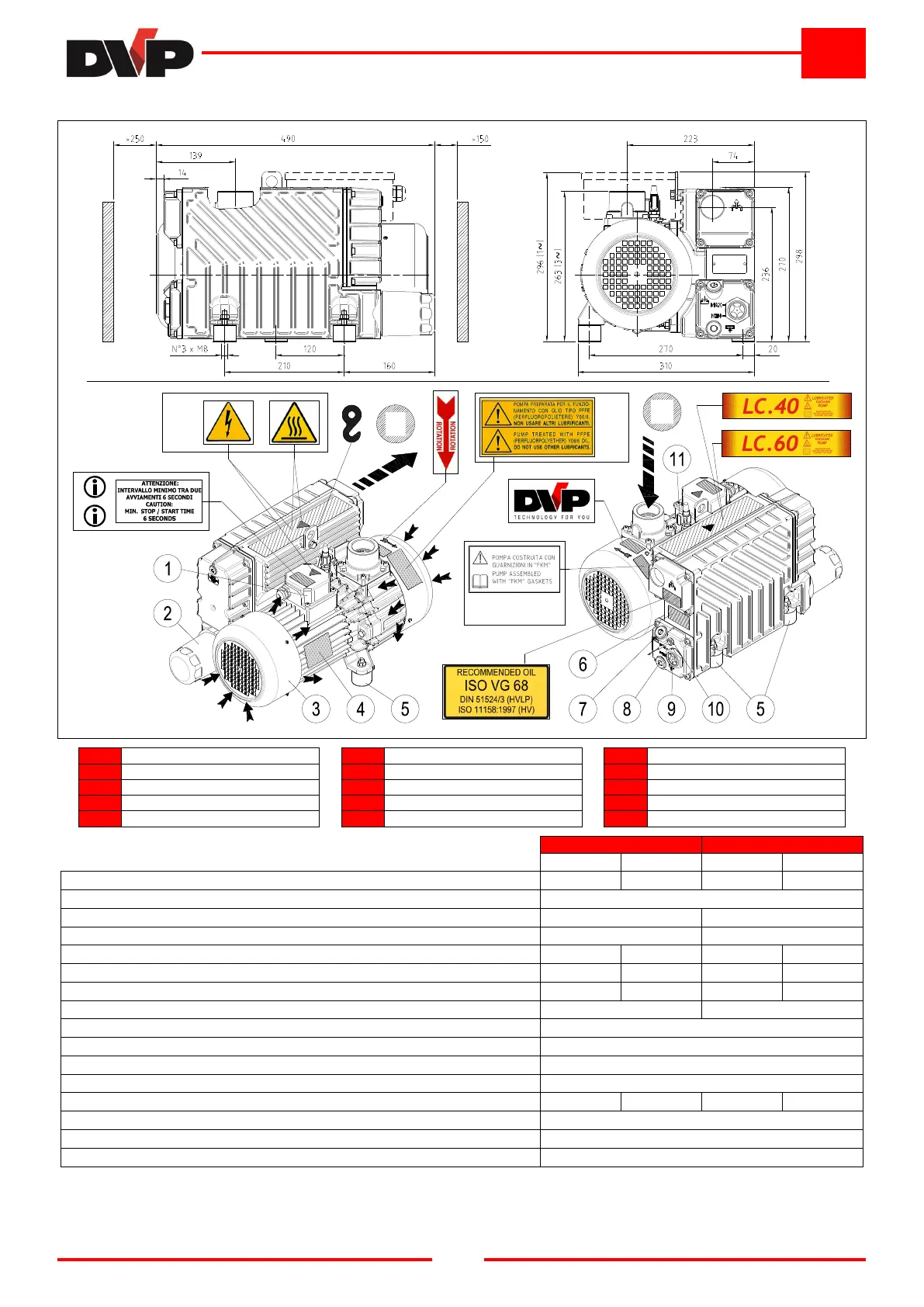
3.4.2 Model: LC 40 – LC 60
A
B
A
Intake
4
Motor rating plate
9
Oil sight glass
B
Air outlet
5
Attachment point
10
Level switch (optional)
1
Terminal board
6
Information plate
11
Gas Ballast ON/OFF
2
Oil filter
7
Oil filler plug
Only present on special versions
3
Motor fun guard
8
Oil drain plug
Only present on 1~ versions
TECHNICAL SPECIFICATIONS
LC 40 LC 60
50 Hz 60 Hz 50 Hz 60 Hz
Inlet capacity m³/h
40 48 60 72
Final pressure (Abs.) mbar - hPa
0,1 **
Max inlet pressure for water vapour mbar - hPa
14 *** 14 ***
Max water vapour pumping rate Kg/h
0,5 *** 0,7 ***
Motor power
kW (1~ / 3~)
1,1 / 1,1 1,35 / 1,35 1,5 / 1,5 1,8 / 1,8
Nominal r.p.m. n/min
1400 1700 1400 1700
Noise level (UNI EN ISO 2151) (K 3dB) dB(A)
64 66 66 68
Weight
kg (1~ / 3~)
46,5 / 42,0 46,0 / 44,0
Type of oil cod. DVP
BV68 (SW60)
Oil quantity Min÷Max dm³
1,0 ÷ 1,5
Pump Intake / Outlet “G
1-1/2 / 1-1/4
Continuous-duty working renge (Abs.) mbar - hPa
400 ÷ 0,1
Operating temperature (room temp. 20°C) °C
65 ÷ 70 70 ÷ 75 70 ÷ 75 75 ÷ 80
Required room temp. for place of installation °C
12 ÷ 40
Ambient temperature for storage/transport °C
-20 ÷ 50
MAX humidity / altitude
80% / 1000m s.l.m. *
(*) Please contact the Manufacturer if environmental conditions are different from those prescribed.
(**) Final pressure (Abs.) with ballast closed.
(***) Final pressure (Abs.) with open Gas Ballast.