Page 10 of 21
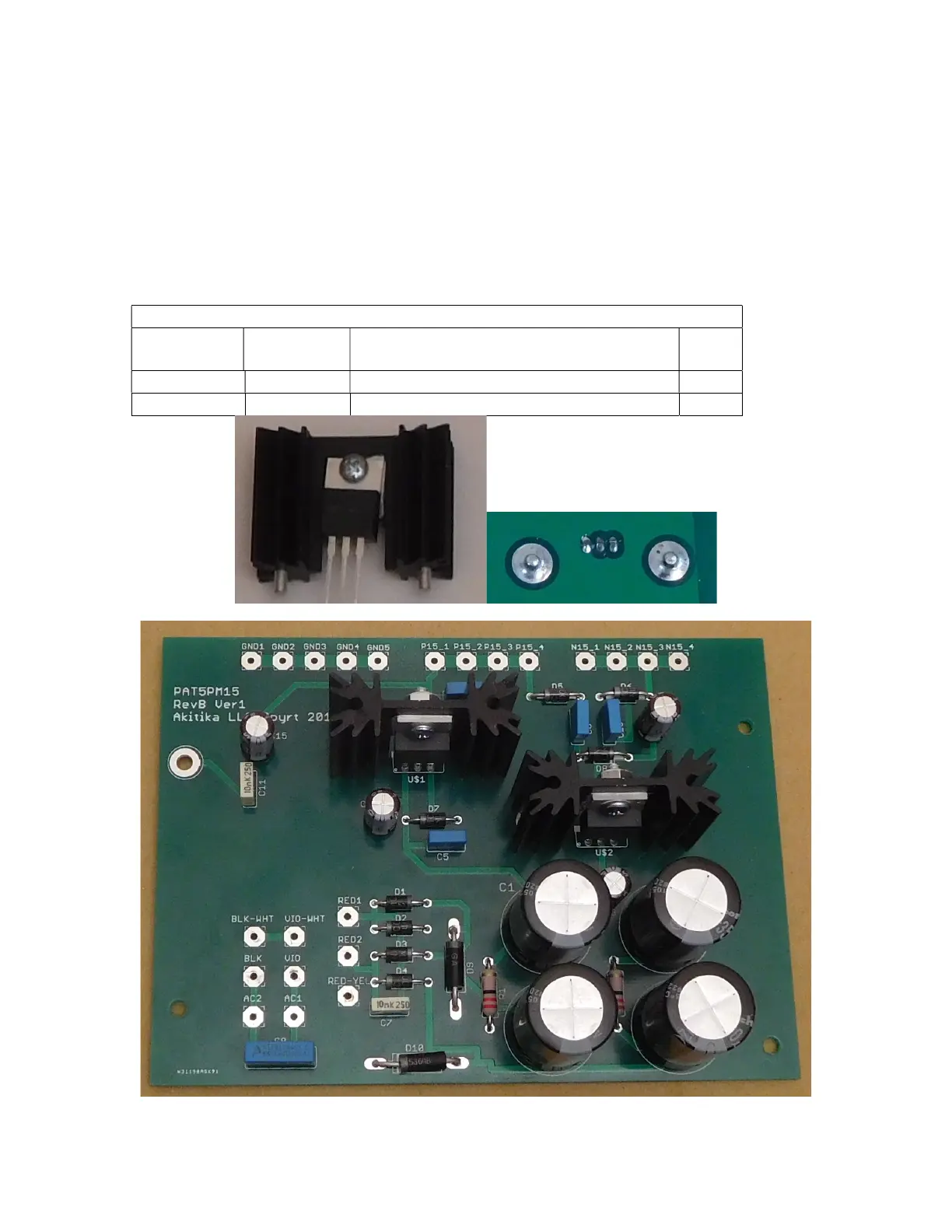
2. Fasten the regulator to the heat-sink using a 4-40x5/16” Phillips head screw and
4-40 keps nut (a nut with a built-in lock washer) as shown in Figure 5.
3. Insert the regulator/heat-sink assembly into the PCB.
4. Turn the board over and solder the cylindrical projections of the heatsinks to the
circular pads on the bottom of the PCB. This will take a lot of heat and solder.
5. Solder the 3 leads of the regulator to their associated pads.
6. Repeat the above process for U$2, the LM7915.
Figure 5 shows the details of the mounting screws and soldering the heat-sink posts on
the bottom of the board.
Designation Value Description Done
Positive 15 Volt Linear Regulator
Negative 15 Volt Linear Regulator
Figure 5-Regulator and Heat Sink mounting screws and soldering mounting posts
Figure 6-Assembled Power Supply