Page 8 of 21
Component Order
You’ll notice that the component designations in the directions don’t go exactly in order.
We have grouped them so that all components with the same value appear together. This
makes assembly easier. You’ll find in the parts kit that similar parts, e.g. 8 1N4004
diodes, are typically (though not always) taped together.
Install the diodes
In general, you install axial leaded components (like the diodes) by placing the body on
the silk screen side of the board, and the leads through the indicated holes. Bend the leads
over on the back of the board to keep the components from falling out until your solder
them in place. Try to bend the leads in a direction that won’t lead to solder bridges
between traces that should remain disconnected.
We recommend the following procedure:
1. Insert all components of the same value or type
2. Bend the leads as described above.
3. Solder the leads on the back of the board.
4. Clip the leads.
Track your progress by placing a checkmark in the done column as you install each
component.
Diodes are polarized, having an anode and a cathode. When you insert the diode, match
the banded end of the diode to the banded end of its representation on the silk screen.
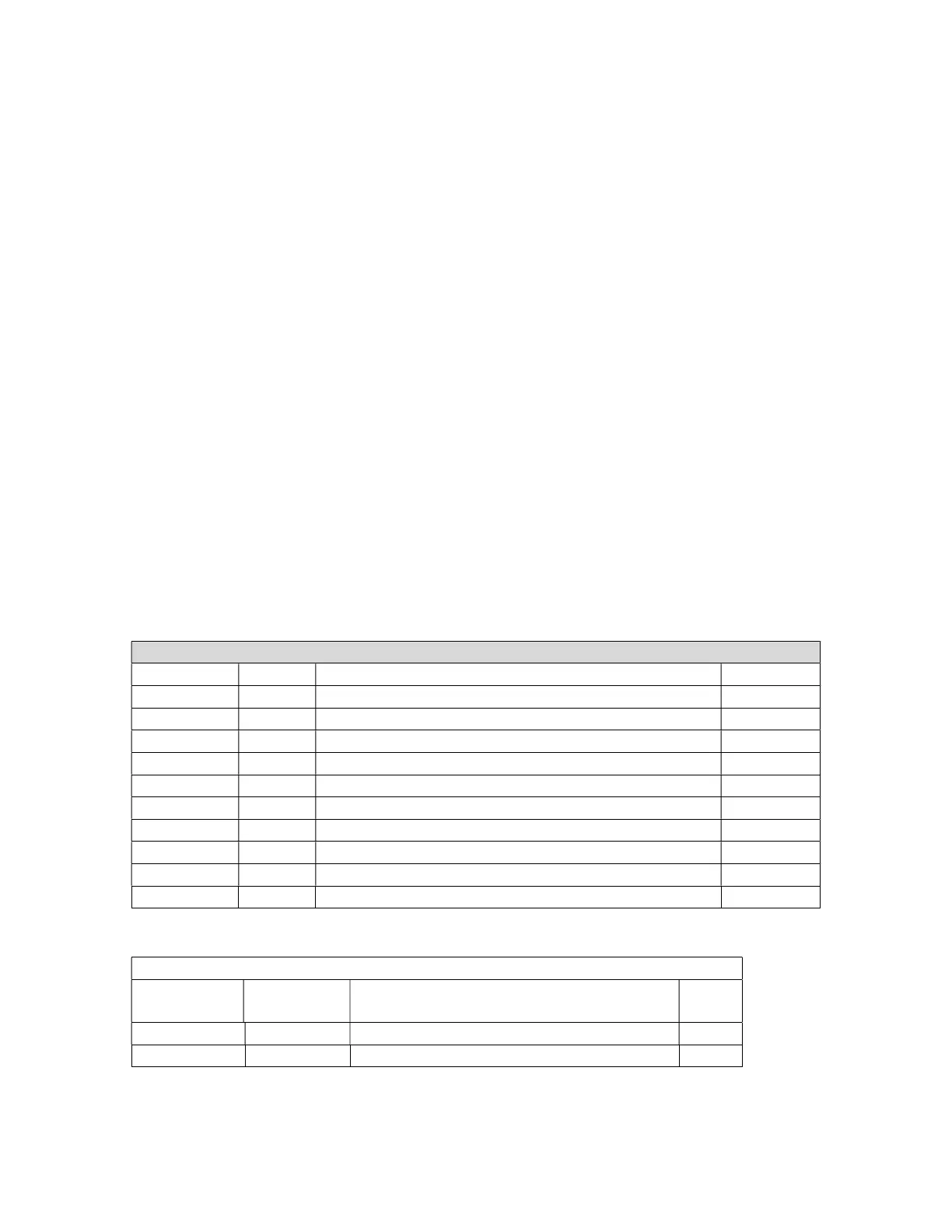
Diodes – watch the polarity! – bend leads to 0.4” width
400 PIV 1 Amp, 1N4004, rectifier diode
400 PIV 1 Amp, 1N4004, rectifier diode
400 PIV 1 Amp, 1N4004, rectifier diode
Amp, 1N4004, rectifier diode
400 PIV 1 Amp, 1N4004, rectifier diode
400 PIV 1 Amp, 1N4004, rectifier diode
400 PIV 1 Amp, 1N4004, rectifier diode
33 Volt, 5 Watt Zener Diode
Install the Resistors
Bend resistor leads to 0.5” width
Designation Value Color Code Done
Red, red, black, gold (1 Watt, 5%)
Red, red, black, gold (1 Watt, 5%)