Page 9 of 21
Install the non-polar Capacitors
These capacitors are not polarized, so it doesn’t matter which way they are installed on
the printed circuits.
Designation Value Description Done
300 Volt Safety Cap, film
Install the Polarized Electrolytic Capacitors
These capacitors have a polarity. If you put them in backwards:
The power supply won’t work
The capacitors may explode sending their insides racing to the outside
Please re-read the above sentence, and double check the capacitor polarity before you
solder them in place!
Please double check the polarity of each
capacitor upon installation
Designation Value Description Done
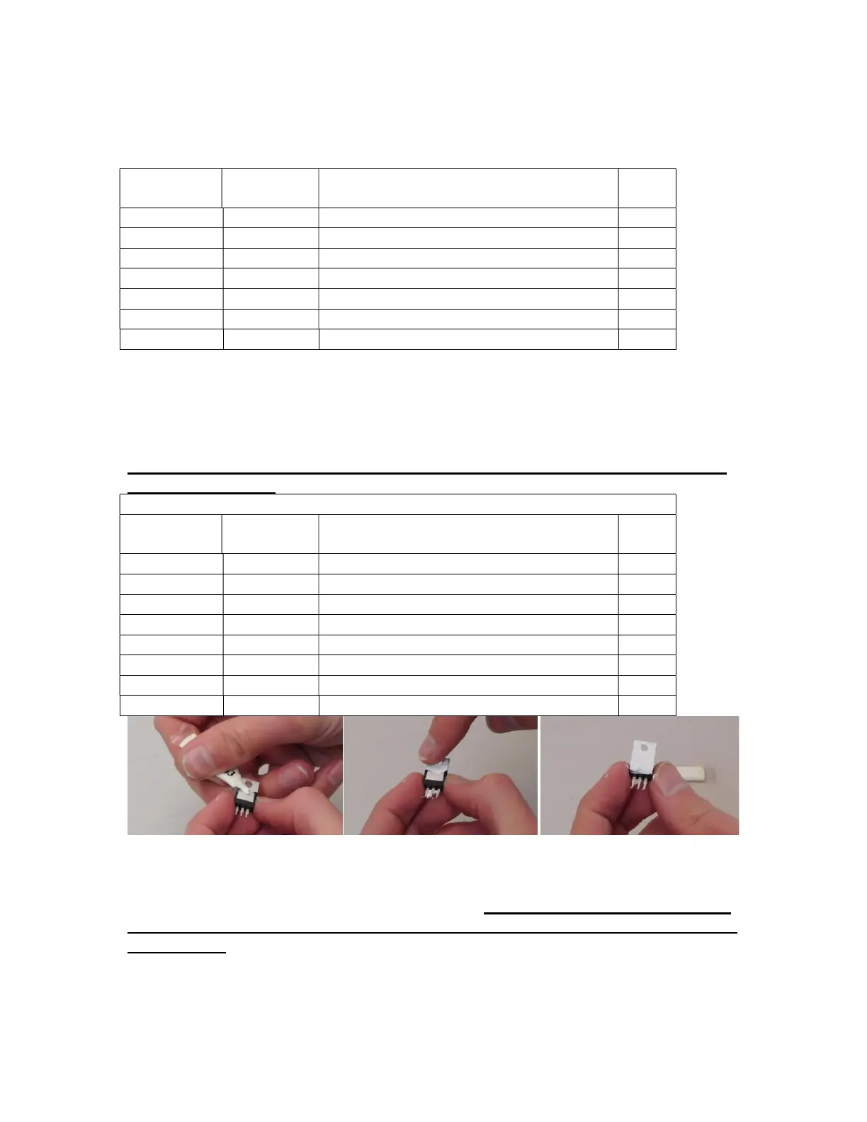
Figure 4-Applying thermal compound
Install the TO-220 Regulators and Heatsinks
There are two regulators, both in TO-220 packages. Be warned…they are different, and
they are not interchangeable. Make sure you double check your work before you solder
them in place.
1. Start with U$1, the µA7815. Spread a thin film of heatsink compound on the back
of the regulator, see Figure 4.