Page 13 of 21
Remove the old power supply
Remove the four screws (two in each bracket) that hold the silver colored
power supply mounting brackets to the
Disconnect Transformer wires from the old PCB
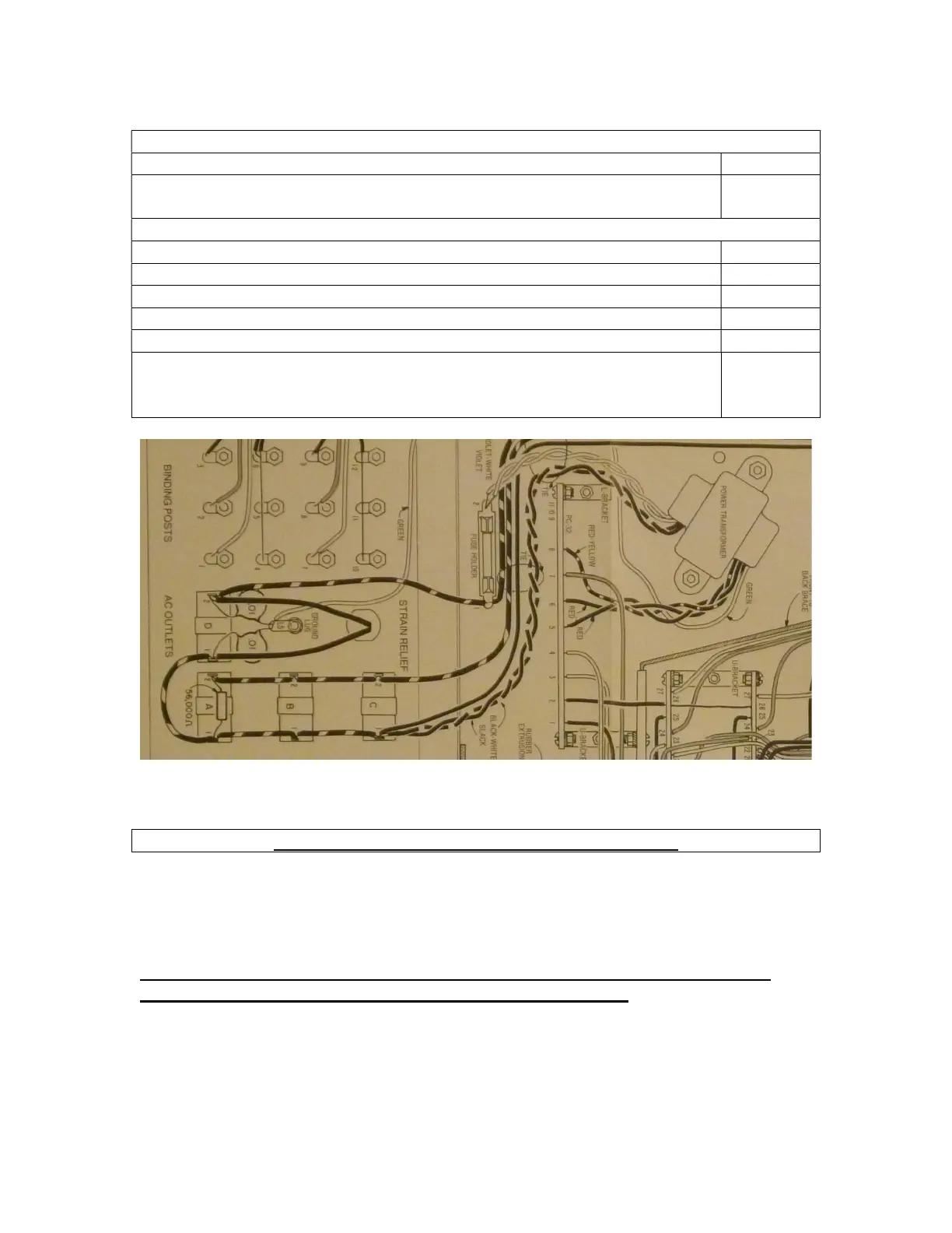
Desolder the two red wires
yellow wire from the old PC board.
Desolder the violet and violet
white wires from the fuse holder.
Disconnect the transformer wires from the chassis
Desolder the black and black-white wires from their connection point on the
convenience outlet. However, make note of this terminal as a wire will be
reconnected here in a later step.
Figure 10-Original Transformer wiring
Connect the Transformer
Make absolutely sure that your PAT-5 is unplugged!
You will re-use the original Dynaco power transformer. In its new connection
arrangement, the total power drawn by the PAT5 drops from 10 Watts to 7 Watts. That’s
because the new arrangement is more efficient than the stock arrangement.
When the new power supply is installed, except for the green shield wire, all of the
transformer wires will terminate on the new power supply PCB.
Connecting the low voltage transformer wires
1. Identify the following 3 transformer wires
a. First red wire
b. Second red wire