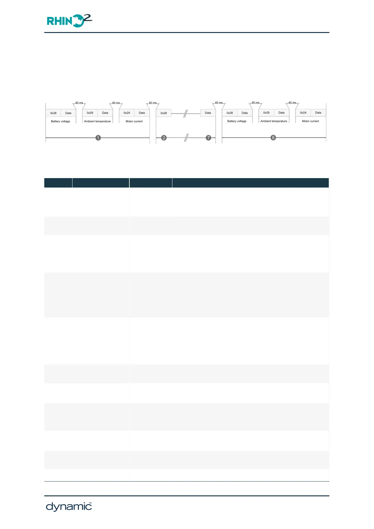
7.7.3.2.7 Packet transmission and timing — 1 Hz Data packet
Data elements are transmitted with a 40 ms delay between each element (see Figure 67).
Unlike the Full Data packet, there is no Dummy element or End of Data Transfer (checksum)
element.
Figure 67: Packet transmission — 1 Hz Data packet example
7.7.3.2.8 Table of data elements
Table 1: Data elements
ID Name Data values Description
0x00 Dummy element 0
The dummy element is sent to wake up the receiving
device. There is a one second delay before the next
element (0x01) is transmitted.
0x01 Start element 2
Indicates the start of the data and corresponds to the
protocol version
0x02 Inhibit status 0–1
(Charger) inhibit status:
0 — no inhibit active
1 — inhibit active
2 — inhibit active and battery charging
0x03 Key switch status 0–2
Indicates the status of the key switch:
0 — key off
1 — key on, normal operation
2 — key on, sleep mode
3 — key on, low power mode
0x04 Active error code
See "HHP
Fault Codes
with sub
codes" on
page 128
Upper nibble (0–F): flash code
Lower nibble (0–F): subcode
0x05
Battery gauge
estimate
0–100 %
Battery gauge
0x06 Speed limit 0–100 %
This is the value of the speed limit input (SLP)
connected to pin TH9
0x07 Driving status 0–1
Indicates driving status:
0 — not driving
1 — park brake released and driving
0x08 Pin TH4 level 0–255
Integer part of voltage on pin TH4. Note that 1
LSBcorresponds to 250 mV.
0x09 Pin TH6 level 0–255
Integer part of voltage on pin TH6. Note that 1
LSBcorresponds to 250 mV.
0x0A Pin TH12 level 0–255
Integer part of voltage on pin TH12. Note that 1
GBK51948 RHINO2
Installation Manual Issue 5
Diagnostics - Page 137
 Loading...

