37CA 252/302/402 M252EN6
ELECTRICAL SYSTEM, FUSES
Main fuses
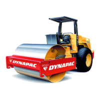
Fig. 64 Engine compartment
1. Starter relay
2. Main fuses
3. Preheater relay
There are three main fuses (2). These are located
behind the battery master disconnect switch. The three
screws need to be unscrewed to remove the plastic
cover.
The fuses are of the flat pin type.
Supply, standard 30 A (Green)
Supply, cab 50 A (Red)
Supply, lighting 40 A (Orange)
The start relay (1) and the engine preheating relays (3)
are also fitted here.
Fuses in the cab
The electric system in the cab is equipped with its own
fuse box, located overhead at the front right part of the
cab.
The figure shows the ampere rating and function of the
different fuses. All fuses are of the flat pin type.
Relays
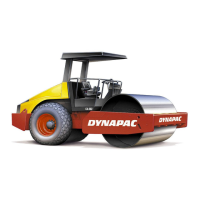
Fig. 65 Instrument panel
12 3
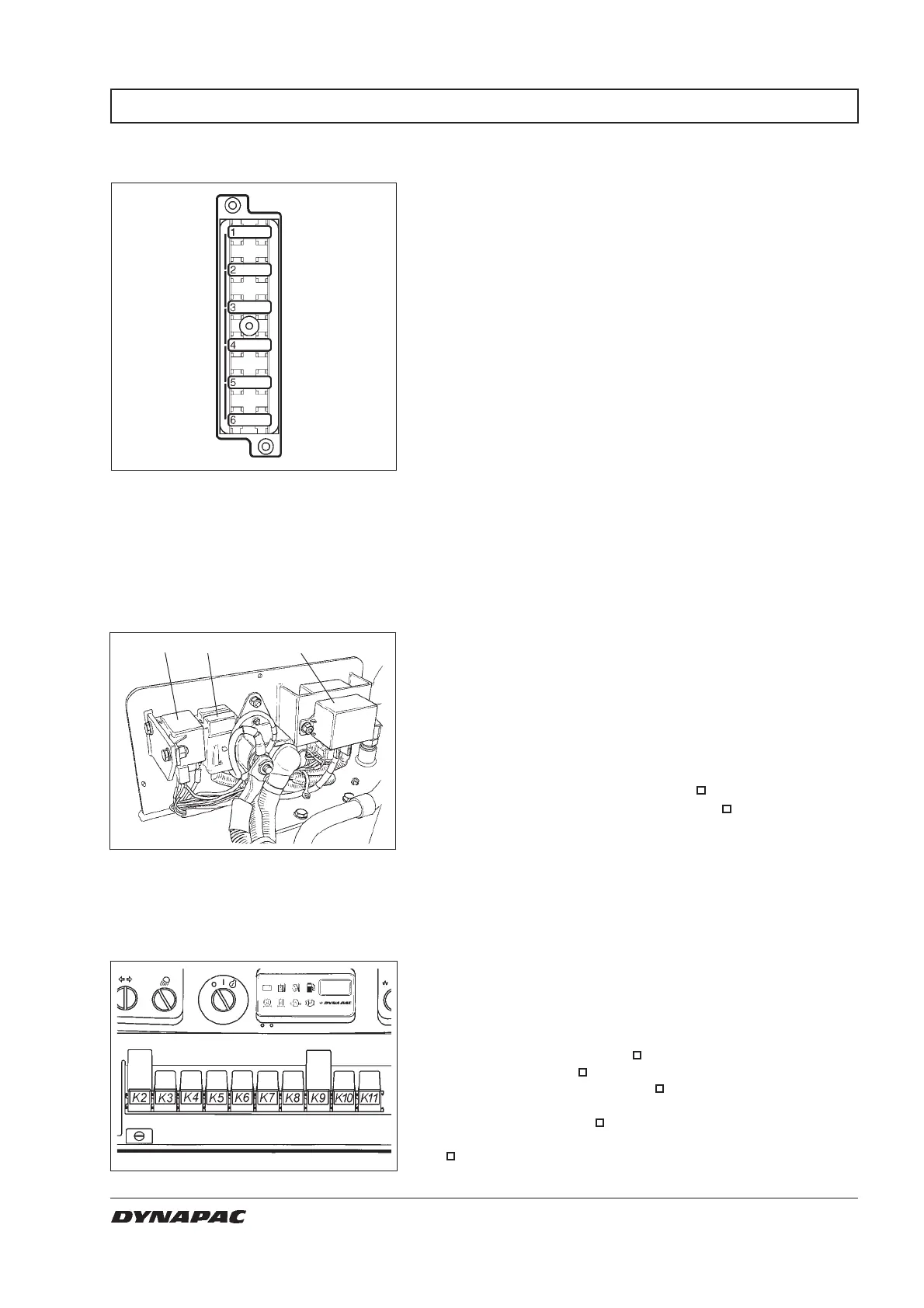
Fig. 63 Fuse box overhead in cab
20A 1. Condenser fans, cab roof
10A 2. Radio
5A 3. Cab interior lighting
25A 4. Air conditioner fan
10A 5. Rear screen wiper/screen-wash
10A 6. Front screen wiper/screen-wash
K2 VBS relay
K3 Main relay
K4 Horn relay
K5 Hourmeter relay
K6 Fuel level relay
K7 Reverse alarm relay
K8 Lights relay
K9 Direction indicator relay
K10 Brakes relay
K11 Air cond. relay
= Optional