14-Introduction
2.4 Interface Denition
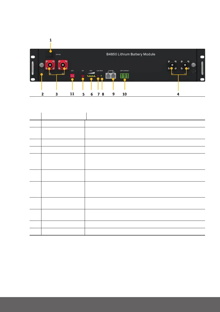
Thissectionelaboratestheinterfacefunctionsofthefrontinterfaceofthedevice.
Fig.2.1-Thesketchofinterface
Pos. NAME DEFINITION
1 Powerswitch OFF/ON,mustbeinthe“ON”statewheninuse
2 Groundconnection
point
Shellgroundconnection
3 Positivesocket Batteryoutputpositiveorparallelpositiveline
4 Negativesocket Batteryoutputnegativeorparallelnegativeline
5 SW(batterywake/
sleepswitch)
Whenthe“OFF/ON”switchbuttonisintheONstate,press
andholdthisbuttonfor3secondstoputthebatteryintothe
power-onorsleepstate.
6 SOC Thenumberofgreenlightsonshowstheremainingbattery
power.SeeTable2-3fordetails.
7 ALM Redlightashingwhenanalarmoccurs,redlightalways
onduringprotectionstatus.Aftertheconditionoftrigger
protectionisreleased,itcanbeautomaticallyclosed.
8 RUN Greenlightashingduringstandbyandchargingmode.Green
lightalwaysonwhendischarging.
9 CAN/485 Communicationport,supportCAN/RS485communication
(factorydefaultCANcommunication)
10 DRYCONTACT /
11 ADD DIPswitch
Tab.2.2-InterfaceDenition