Page 5
4.0 Meter Installation (Continued)
4.2 Main Power Board Connections (Continued)
STEP 3: Wire Entry (continued)
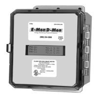
Outdoor applications require the use of the optional NEMA 4X
enclosure. The same principles outlined for indoor meter installations
as defi ned in the aforementioned paragraph carry over and apply to
outdoor installations with one exception. This exception is that the
conduit and fi ttings for outdoor installations require an outdoor material
rating.
STEP 4: Unit MAINS Wiring (Voltage Wiring Connections)
Remove the clear shield located over terminal block TB1 on the main
power board. This shield can be removed by pressing in on each
locking tab located at the top of each standoff. While pressing the tabs
inward, lift the shield from the standoffs. Wire each connection to
Terminal Block TB1 with stranded wire 14-12 AWG, rated at 600 VAC.
Strip back all wire insulation to expose between 1/4” and 3/8” of the
copper conductors. Gently twist each wire to prevent fraying. Insert the
conductors into their respective terminal block position and tighten down
the terminal block screw to securely fasten the conductor. Terminal
block TB1 is clearly labeled PHASE A, PHASE B, PHASE C and
NEUTRAL. Phase C is not used on single phase circuits.
Connect the NEUTRAL wire to the appropriate terminal block position.
Connect the AC mains power wires (Phase A and Phase B) to
their respective positions as labeled on terminal block TB1. Also connect
the neutral wire.
After all conductors are connected to their respective terminal block
positions and tightened down, verify that each terminal block screw
is securely fastened by gently tugging on each conductor. Verify no
conductor wires are frayed or are shorting to adjacent terminal block
positions.
STEP 5: External Switch Mechanism/In-Line Fuse Installation
To ensure a safe installation, the Class 1000 meter requires an
external switch mechanism, such as a circuit breaker, be installed on
the Class 1000 MAINS input wiring. The switch mechanism must be
installed in close proximity to the meter and easily reachable for the
operator. This device must also be marked as the disconnecting device
for the Class 1000 meter.
 Loading...