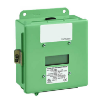
Page 6
4.0 Meter Installation (Continued)
4.2 Main Power Board Connections (Continued)
STEP 5: External Switch Mechanism/In-Line Fuse Installation (Continued)
Install 1/10 Amp Slow Activation inline fuses with the suitable voltage
rating for each conductor phase at the MAINS input to the meter. The
fuses must be labeled to indicate voltage and current rating as well as
element characteristics. The fuse element must be slow activating type.
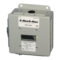
STEP 6: Once the MAINS wiring is complete, replace the clear lexan
protective shield over terminal block TB1 and close the enclosure front
panel. Secure the enclosure cover using the locking mechanism.
Activate the external circuit breaker or equivalent switch to apply AC
MAINS power to the unit.
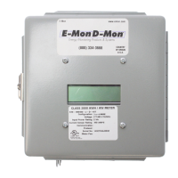
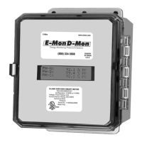
The Class 1000 meter display should turn on and indicate total kWh
accumulation reading.
NOTE: The unit display, clock and other critical confi guration parameters will be
reset once the unit installation and wiring is complete.
STEP 7: Using an AC Voltmeter, verify the input voltage readings are within the
limits specifi ed below.
NOTE: Single Phase systems, the voltages are measured Phase to Neutral.
Meter Input Voltage Nominal Voltage Limits (+/- 10%)
Confi guration
120/208V, 2 Ph, 3 Wire 120 VAC 108 to 132 VAC
120/240V, 2 Ph, 3 Wire 120 VAC 108 to 132 VAC
STEP 8: Remove power from the unit by de-energizing the external switch.
 Loading...