protection & status
indication/comments
DC 12 V/24 V
(DC 9 V … 32 V)
short-circuit and over-current
protection: Current limitation and
electronic safety shutdown; motor
function: two H-bridges (O1&O2,
O6&O7); high current function: 20
A outputs via parallel connection of
two load outputs; dimming function
with adjustable frequency
based on SAE J1939, galvanically
isolated
switch, momentary switch,
...
control inputs, switching to ground
battery, charger, sensor, ...
battery current measurement
± 60 mV,
note: when monitoring the battery,
it must be ensured that
PLUS/MINUS are correctly
connected.
monitoring of tank levels
ground for
multifunctional
inputs
caution: ground of load outputs
GND
O
must be connected
externally!
short-circuit and over-current
protection: Current limitation and
electronic safety shutdown;
dimming function with adjustable
frequency
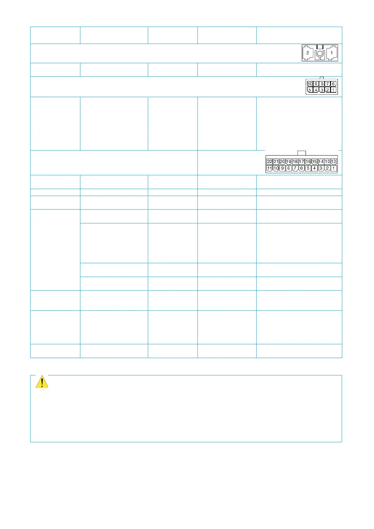
Tabel 5: Inputs, outputs and interfaces of the PowerPlex® Compact Module
Caution
To avoid inadvertent short circuits, please ensure that the module is disconnected from the power
supply before you establish connections.
The ground connections GND
I
on the module are only for the multifunctional inputs (X3: I1 - I8). The
ground connection GND
O
for an output (X2: O1 - O10; X3: O1 - O4) must be installed externally.
Please observe correct polarity for connection and wiring of the device.