19
Fig. 8: Dimensions of the PowerPlex® Compact Module
All cables are connected to the module from below. This has to be considered in the planning stage and ensures
ease of mounting, preventing a possible kinking of the cables.
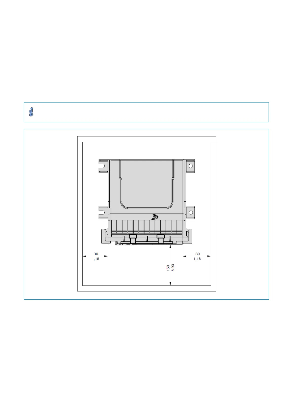
5.5. Dimensions and space requirements
According to EMC conditions there must always be sufficient space between the different electrical devices. Space
requirement of a device depends on its dimensions shown in Fig. 9.
Delivery of a standard PowerPlex
®
Compact Module does not include any mating plugs. They can be ordered
separately as accessories XPP-CP-130:
Information
The protection degree IP22 is achieved when the PowerPlex
®
Compact Module is installed vertically
with the terminals pointing downwards.
Fig. 9: Installation dimensions of the PowerPlex® Compact Module
5.6. Mounting of the device
Before you start installation, please make sure that
• the installation site was selected under consideration of the product-specific requirements
• the cable connections were identified correctly and cable laying was thoroughly planned
• the power supply was disconnected and protected against inadvertent reset