10
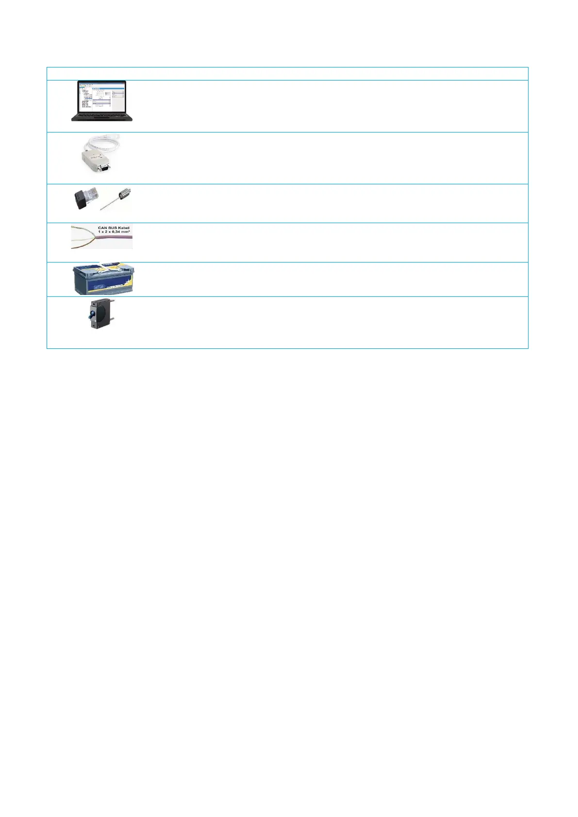
More components required for setting up a PowerPlex
®
system are shown in .
PowerPlex
®
Suite
Configuration software for defining addresses, characteristics and functions of the
PowerPlex
®
modules, assignment of the inputs and outputs to the modules and
execution of system tests and analyses.
CAN-USB converter plus driver
CAN-USB adapter for connecting the CAN bus hardware to the USB interface of the
computer with the PowerPlex
®
configuration software and/or to the USB interface of
a touch panel which could be connected to the PowerPlex
®
.
Terminating resistors
Two 120 Ω resistors terminate the CAN bus network, one on each end of the CAN
bus.
CAN bus cable
A trunk CAN bus cable in pairs with two conductors (CAN-H and CAN-L) and the
shield (SHLD) connect two PowerPlex
®
modules with each other.
Power supply
12 V DC or 24 V DC battery voltage supply
Line protection
Protection of the L (+) connection from a PowerPlex
®
module to the battery or to the
CAN bus.
Recommendation: Thermal-magnetic E-T-A 8345 circuit breaker type.
Table 2: Additional accessories