9
PowerPlex
®
communication is based on the CAN bus principle by means of “nodes”, which communicate with
each other via a serial 2-wire connection. Hence the key components of a PowerPlex
®
system are these nodes
distributed over the vehicle or boat. The overall PowerPlex
®
term for these interconnected nodes is “module".
Various hardware components are required for installation and start-up of a PowerPlex
®
system:
Please check the delivered components upon receipt about completeness. You require the following hardware
components for installation and start-up of a PowerPlex
®
system:
• one or more PowerPlex
®
modules (e.g. DC Power Module, DC Mini Module) that meet application-specific
requirements
• USB-CAN converters (cable and driver) for transferring the configuration
• USB cables for the USB service interface for transferring application-specific user interfaces onto
PowerPlex
®
Touch Panels.
In addition, you require a CAN bus cable for connecting the PowerPlex
®
components to the bus. Many
manufacturers offer standard cables for this purpose. For more information on the required cable properties please
see chapter 7 of the manual.
PowerPlex
®
reliably and precisely connects, regulates, controls and monitors electrical loads, switches and
sensors via CAN. It controls status indications, operating conditions and execution of commands. Perfectly
matched software and hardware components offer a comprehensive total solution with maximum potential of
individualisation.
Each module protects the loads and cable harnesses against overcurrent. In addition the modules collect data of
level sensors and temperature sensors as well as of shunts. Usually a PowerPlex
®
system consists of several
modules of different kinds. The selection depends on the size of the electrical system to be monitored and
controlled as well as of the current ratings of the loads.
Use our PowerPlex
®
Configuration Software to “programme” various control configurations. As requested, you
can store them on the computer and load them into various PowerPlex
®
control systems. As soon as a
PowerPlex
®
configuration has been completed, it will be transferred to the PowerPlex
®
modules (”nodes”) via the
CAN bus interface. Via this CAN bus interface you also connect the PowerPlex
®
software for testing, analysing
and debugging purposes of the PowerPlex
®
installation.
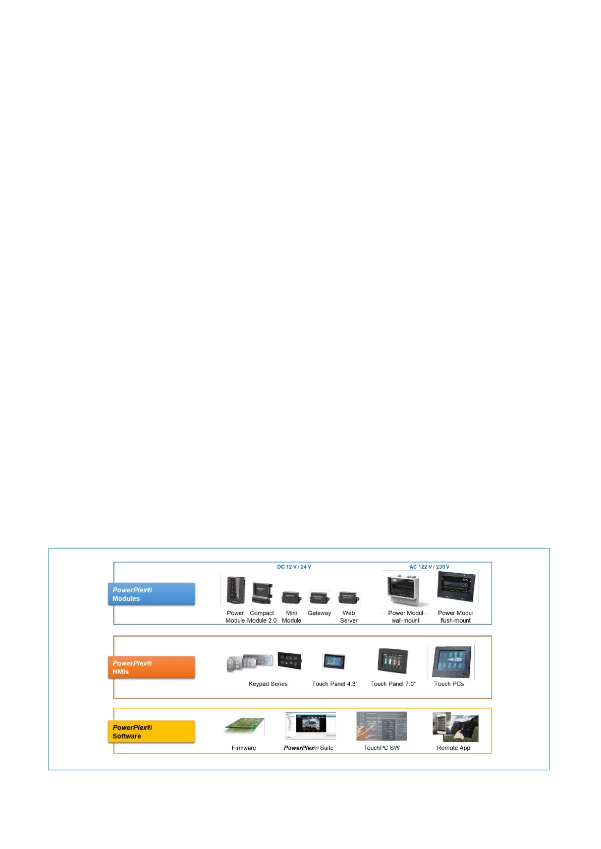
Fig. 3 shows the entire PowerPlex
®
product range to enable you to design your own PowerPlex
®
system solution: